Damped micromechanical device

Inactive Publication Date: 2003-11-27
COHERENT INC
View PDF7 Cites 23 Cited by
  • Summary
  • Abstract
  • Description
  • Claims
  • Application Information

AI Technical Summary

Benefits of technology

0008] The present invention, in one embodiment, is a damped micromechanical device. The device includes a body having substantially parallel first and second walls at least partially defining an internal chamber. A fluid and a movable structure are disposed in the chamber. The movable structure is movable in a direction substantially parallel to the first and second

Problems solved by technology

Micromechanical devices are prone to the effects of externally-imposed mechanical vibration, in that any acceleration imposes a force on the moving mass of the device that tends to move the device an amount dependent on the suspension stiffness in the direction of the acceleration.
These balanced designs tend to reduc

Method used


Image

  • Damped micromechanical device
  • Damped micromechanical device
  • Damped micromechanical device

Examples


Example

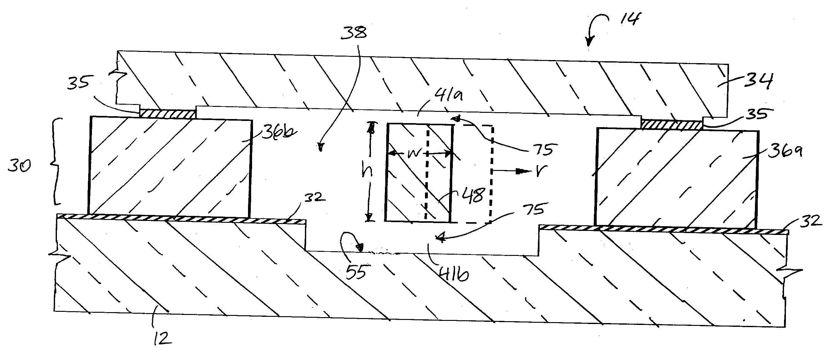
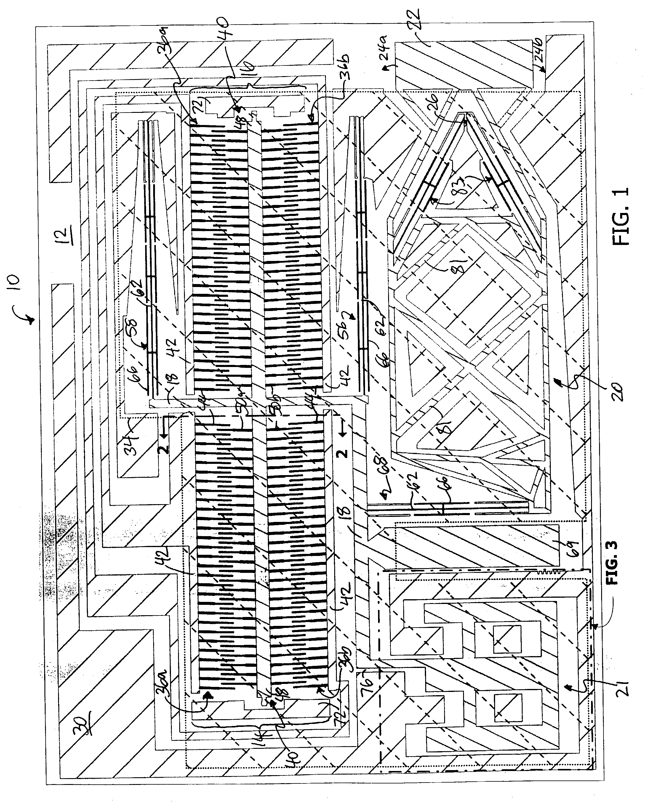
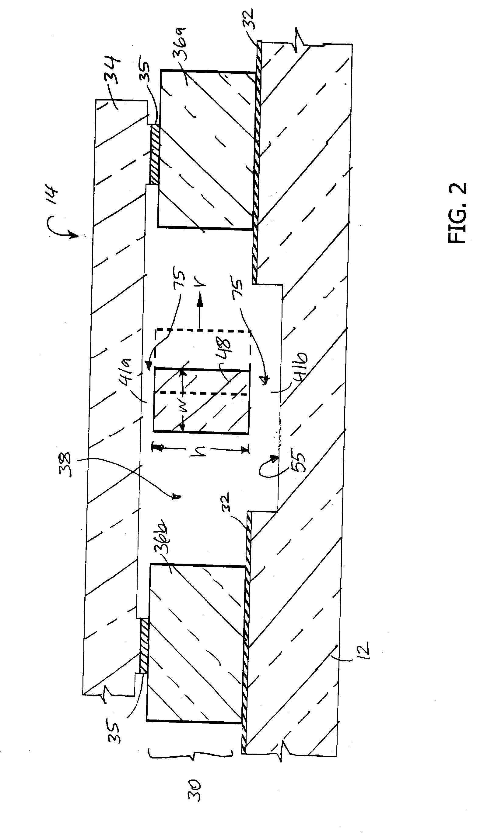
[0015] The damped micromechanical device 10 of the present invention can be an actuator that includes a base or planar substrate 12, first and second microactuators or motors 14 and 16, a shuttle 18, and a pivot assembly 20 (see FIG. 1). In one embodiment, the damped micromechanical device 10 further includes a dashpot 21 for damping vibration within the device 10. The microactuators 14 and 16 are coupled to the pivot assembly 20 via the substantially rigid shuttle 18, such that actuation of the microactuators 14 and 16 cause a corresponding rotation of the pivot assembly as further detailed below. The pivot assembly is connected to a movable platform 22, which moves in an arc 24a or 24b about a pivot point 26. A movable component is connected to the movable platform 22 and is articulated by actuation of the microactuators 14 and 16. In one embodiment, the movable component is a collimating lens for use in a telecommunications system.

[0016] The damped micromechanical device 10, in o...


PUM


Abstract

A damped micromechanical device useful for adjusting optical components, positioning transducers, and sensing motion. The micromechanical device includes a top cap that helps create an area of restricted fluid flow to increase mechanical damping of the device and minimize the response of the structure to mechanical perturbations. The micromechanical device is constructed to cause piston-like Poiseuille flow through controlled gaps within the actuator. By controlling the gap dimensions, the amount of damping can be adjusted.

Description

[0001] This application claims priority to U.S. provisional patent application No. 60 / 335,146 filed Feb. 8, 2002, the entire content of which is incorporated herein by this reference.SCOPE OF THE INVENTION[0002] The present invention relates generally to micromechanical devices and more particularly to a mechanically-damped micromechanical actuator.[0003] Micromechanical devices such as microactuators are used for many purposes, including moving and adjusting optical components. Similar structures can be used as sensors for acceleration. An example of a linear microactuator, designed to translate a mirror in and out of a beam of light, is described in issued U.S. Pat. No. 5,998,906. In this design, the devices were activated against mechanical stops and were relatively immune from the effects of vibration. The mechanical dynamical behavior of micromechanical structures can be characterized as having an amplitude and phase response as a function of mechanical drive frequency, as disp...

Claims


Application Information

Patent Timeline
IPC IPC(8): B81B3/00F16M1/00G02B26/08
CPCB81B3/0078G02B26/0841B81B2201/058B81B2201/033
Inventor YASUMURA, KEVIN Y.GRADE, JOHN D.JERMAN, JOHN H.
Owner COHERENT INC
Why Eureka
Try Eureka