Systems and methods for imaging using radiation from laser produced plasmas

a radiation source and plasma technology, applied in the field of targets, can solve the problems of large focal spot, large spectral range, and many image quality limitations

Active Publication Date: 2009-06-30
BOARD OF RGT NEVADA SYST OF HIGHER EDUCATION ON BEHALF OF THE UNIV OF NEVADA RENO
View PDF10 Cites 24 Cited by
  • Summary
  • Abstract
  • Description
  • Claims
  • Application Information

AI Technical Summary

Benefits of technology

[0014]Particular embodiments of the present disclosure provide imaging methods. According to one implementation, k-alpha x-rays are produced by irradiating a target with a laser. The targets are hollow and have a metal layer. The targets may have straight or curved surfaces, or a combination thereof. In more specific examples, the hollow targets have an internal apex of less than about 15 μm, such as less than about

Problems solved by technology

However, such X-ray tubes can pose several limitations on image quality including large focal spot, broad spectral range, inadequate output and long radiation duration.
A major problem with typical current X-ray emission techniques in medicine is the broadband energy spectrum that contributes to patient dose while not improving the resulting image.
Furthermore, the, typically, picosecond duration of the X-ray emission coupled with a high repetition rate laser can produce a high fluence of X-rays in a very short period of time.
However, the silicon included in such targets typically interferes with energy focus

Method used


Image

  • Systems and methods for imaging using radiation from laser produced plasmas
  • Systems and methods for imaging using radiation from laser produced plasmas
  • Systems and methods for imaging using radiation from laser produced plasmas

Examples


example 1

Mammography

[0094]A mammography imaging system is set up generally as shown in FIG. 8. The laser is a Ti-Sapph laser having an irradiance of 1·1019 W / cm2, 400 mJ, and a pulse length of 40 fs. The focal spot size is 10 μm. The target is a gold coated, free-standing cone having an internal apex of less than about 1 μm. The thickness of the gold coating is about 10 μm. The target is selected, and the imaging system components selected, to produce k-alpha radiation having energies in the range of 15-25 keV.

[0095]The focal point of the x-ray beam exiting the exit aperture is determined. An x-ray transparent plate is mounted at the focal point of the x-ray beam. In a particular example, a Fuji ST-VA image plate is placed in line with the transparent plate.

[0096]A breast of a patient is exposed and compressed against the x-ray transparent plate. The target is irradiated with the laser. The plate is read using a Fuji FCR-5000 image plate reader. The resulting image is assessed in order to di...

example 2

Phase Contrast Imaging of a Mouse

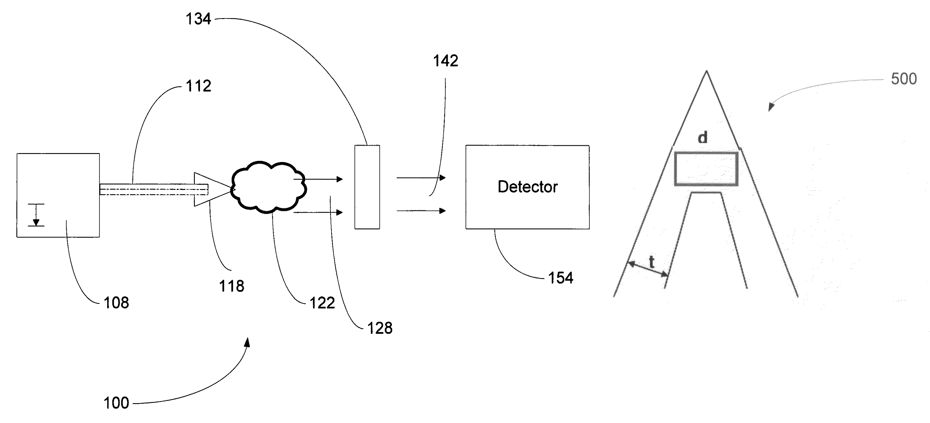
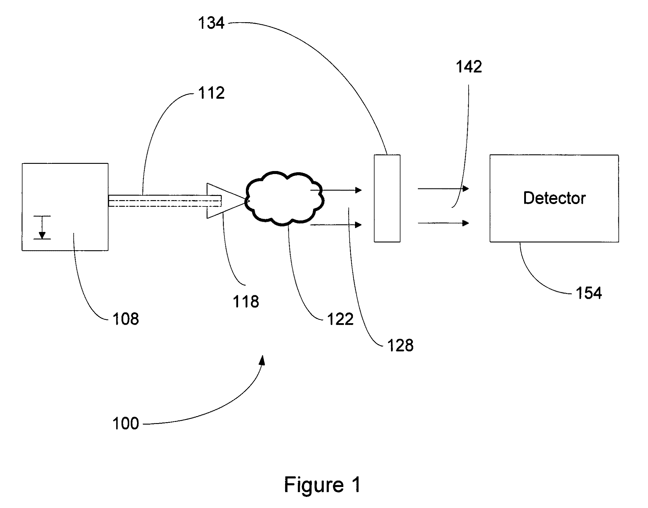
[0097]A phase contrast imaging system is set up generally as shown in FIG. 1. The laser is a Ti-Sapph laser having an irradiance of 1·1019 W / cm2, 400 mJ, and a pulse length of 40 fs. The focal spot size is 10 μm. The target is a gold coated, free-standing cone having an internal apex of less than about 1 μm. The thickness of the gold coating is about 10 μm. The target is selected, and the imaging system components selected, to produce k-alpha radiation having energies in the range of 10-20 keV. The detector is a PI-SCX CCD camera (Princeton Instruments, Trenton, N.J.) coupled to a Gd2SO2 scintillator optimized for radiation having energies of 10-20 keV.

[0098]The focal point of the x-ray beam exiting the target is determined. The mouse is placed at the focal point of the x-ray beam. The distance between the mouse and the CCD camera is 90 cm.

[0099]The mouse is irradiated with the laser and x-ray phase shift and x-ray absorption are measured. The result...

example 3

Time-Gated Imaging of a Mouse

[0100]An imaging system is set up generally as shown in FIG. 1. The laser is a Ti-Sapph laser having an irradiance of 1·1019 W / cm2, 400 mJ, and a pulse length of 40 fs. The focal spot size is 10 μm. The target is a gold coated, free-standing cone having an internal apex of less than about 1 μm. The thickness of the gold coating is about 10 μm. The target is selected, and the imaging system components selected, to produce k-alpha radiation having energies in the range of 10-25 keV. The detector is a Kentech x-ray streak camera with a time resolution of about 50 ps read out using a La Vision FlameStar IIF CCD camera (LaVision, Inc., Ypsilanti, Mich.), as described in Gratz et al., IEEE J. Sel. Top. Quantum Electron. 2, 1041 (1996), incorporated by reference herein in its entirety.

[0101]The flux of x-rays in the x-ray beam exiting the target is determined. The mouse is placed in a rotating cage at an appropriate point in the x-ray beam. The detector is plac...


PUM


Abstract

In particular embodiments, the present disclosure provides systems and methods for imaging a subject using radiation emitted from a laser produced plasma generating by irradiating a target with a laser. In particular examples, the target includes at least one radiation enhancing component, such as a fluor, cap, or wire. In further examples, the target has a metal layer and an internal surface defining an internal apex, the internal apex of less than about 15 μm, such as less than about 1 μm. The targets may take a variety of shapes, including cones, pyramids, and hemispheres. Certain aspects of the present disclosure provide improved imaging of a subject, such as improved medical images of a radiation dose than typical conventional methods and systems.

Description

CROSS REFERENCE TO RELATED APPLICATIONS[0001]This application claims the benefit of, and incorporates by reference, U.S. Provisional Patent Application No. 60 / 789,841 filed Apr. 5, 2006.STATEMENT OF GOVERNMENT SUPPORT[0002]This invention was made with United States Government support under grants DE-FC52-01NV14050, and DE-FC52-06NA27616 awarded by the National Nuclear Security Administration of the U.S. Department of Energy. The United States Government has certain rights in the invention.TECHNICAL FIELD[0003]The present disclosure relates to targets and their methods of fabrication. In particular examples, the present disclosure provides methods of fabricating metal targets useable as laser targets in high-energy laser-physics.BACKGROUND[0004]Current medical imaging techniques typically employ standard X-ray tubes. However, such X-ray tubes can pose several limitations on image quality including large focal spot, broad spectral range, inadequate output and long radiation duration.[...

Claims


Application Information

Patent Timeline
IPC IPC(8): H01J35/08H05G1/00
CPCA61B5/0091A61B5/4312H05G2/001
Inventor RENARD-LE GALLOUDEC, NATHALIECOWAN, THOMAS E.SENTOKU, YASUHIKORASSUCHINE, JENNIFER
Owner BOARD OF RGT NEVADA SYST OF HIGHER EDUCATION ON BEHALF OF THE UNIV OF NEVADA RENO
Why Eureka
Try Eureka