Suction valve

a technology of suction valve and end cap, which is applied in the direction of mechanical equipment, transportation and packaging, functional valve types, etc., can solve the problems of affecting the operation of the valve, the end cap of the valve is known to crack and fail under load, and achieves the effects of reducing stress zones, substantial cost savings, and low manufacturing cos

Inactive Publication Date: 2007-02-06
GARDNER DENVER INC
View PDF19 Cites 29 Cited by
  • Summary
  • Abstract
  • Description
  • Claims
  • Application Information

AI Technical Summary

Benefits of technology

[0004]In light of the problems associated with fluid ends of pumps used for hydraulic fracturing, it is a principal object of the invention to provide a suction valve that reduces the likelihood of proppant being knocked out of suspension to create a blockage. The suction valve of the present invention, thus, offers few impediments to flow through a fluid end when open so that fracturing fluids can flow smoothly through it. As a result, fracturing fluids with higher than normal concentrations of suspended proppants can be pumped with substantial cost savings to the user. Unlike a conventional, wing-guided valve, no spring retainer projects into the plunger bore to close the open valve and, sometimes, undesirably knock out proppants.
[0005]It is another object of the invention to provide a suction valve of the type described that may be seated in a relatively shallow pocket in a fluid end. A valve pocket of shallow depth, of course, requires less load-bearing material to be removed from the body of a fluid end than does one of greater depth like that required for a wing-guided valve. It is less likely, then, that a fluid end configured to receive the suction valve of the present invention will fail from the development of excessive internal loads and stresses.
[0006]It is a further object of the invention to provide a suction valve of the type described that utilizes a valve seat that abuts its supporting surface, i.e., a seat deck, at a shallow incline rather than at right angles as has been commonly done. This slope of about 30° has been found to significantly reduce zones of stress transmitted through a fluid end. It is along such zones that fluid ends have been known to crack and fail under load.
[0007]It is an object of the invention to provide improved elements and arrangements thereof in a suction valve for the purposes described which is relatively lightweight in construction, inexpensive to manufacture, and dependable in use.
[0008]Briefly, the suction valve in accordance with this invention achieves the intended objects by featuring a valve seat and a piston movably joined to the valve seat. The piston has a head for engaging the top surface of the valve seat and a stem extending downwardly from the head through the valve seat. A streamlined valve guide is positioned adjacent the bottom surface of the valve seat and slidably receives the stem. A valve keeper is fitted upon the stem such that the valve guide is disposed between the valve seat and the valve keeper. A keeper pin is slidably positioned within a transverse aperture in the stem and abuts the bottom of the valve keeper. A compressed spring is positioned between, and exerts opposing forces upon, the valve guide and the valve keeper so as to normally retain the head of the piston in engagement with the top surface of the valve seat. Means are provided for preventing the unintentional separation of the keeper pin from the stem and keeper.

Problems solved by technology

Unlike a conventional, wing-guided valve, no spring retainer projects into the plunger bore to close the open valve and, sometimes, undesirably knock out proppants.
It is along such zones that fluid ends have been known to crack and fail under load.

Method used


Image

  • Suction valve
  • Suction valve

Examples


Embodiment Construction

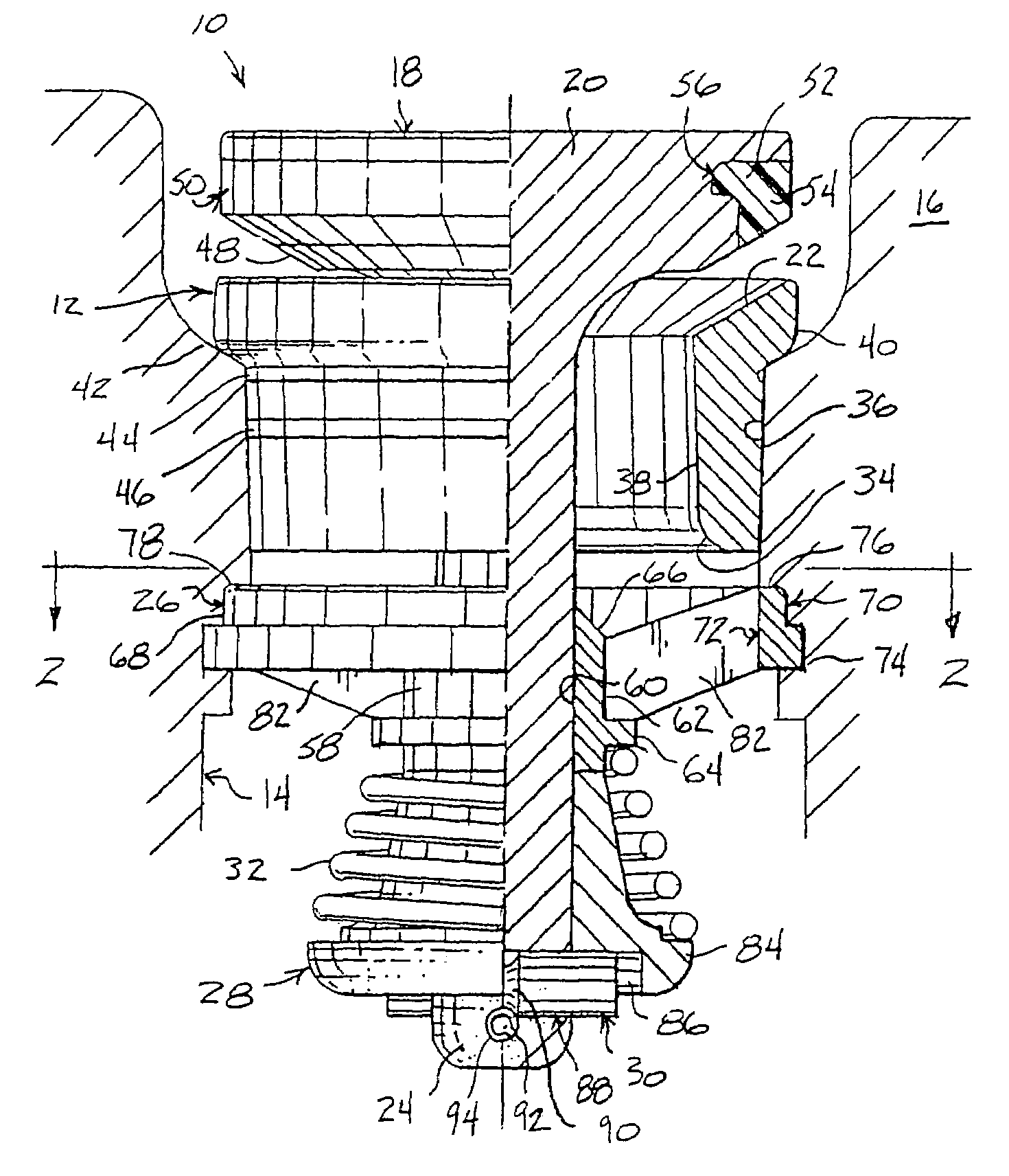
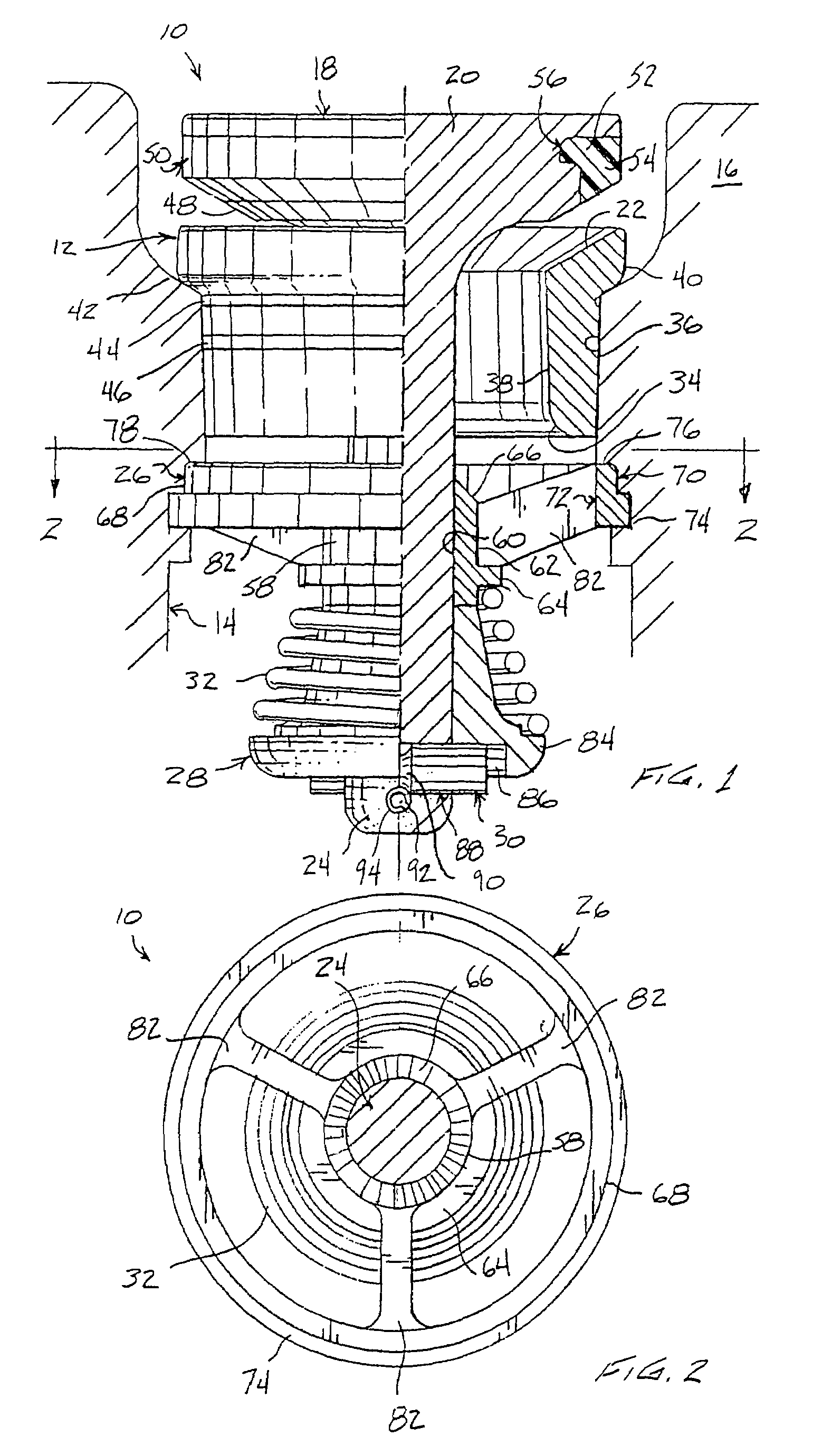
[0014]Referring now to the FIGS., a suction valve in accordance with the present invention is shown at 10. Valve 10 includes a valve seat 12 for positioning in a suction passage 14 of a fluid end 16 and a piston 18 for controlling the flow of fluid through passage 14. Piston 18 has a head 20 for engaging the top surface 22 of seat 12 and a stem 24 extending downwardly from head 20 through seat 12. The bottom of stem 24 extends through a valve guide 26 positioned beneath valve seat 12. A valve keeper 28 is fitted upon the bottom of stem 24 and is retained there by a keeper pin 30. A compressed spring 32 is positioned between guide 26 and keeper 28 to normally retain head 20 in engagement with seat 12 to prevent fluid flow through passage 14.

[0015]Valve seat 12 is a hollow cylinder or tube with top and bottom surfaces 22 and 34 that are shaped to reduce turbulence. As shown, top surface 22 is beveled such that it slopes downwardly and inwardly toward the center of seat 12 at an angle ...


PUM


Abstract

A suction valve including a valve seat and a piston movably joined to the valve seat. The piston has a head for engaging the top surface of the valve seat and a stem extending downwardly from the head through the valve seat. A valve guide is positioned adjacent the bottom surface of the valve seat and slidably receives the stem. A valve keeper is fitted upon the stem such that the valve guide is disposed between the valve seat and the valve keeper. A keeper pin is slidably positioned within a transverse aperture in the stem and abuts the bottom of the valve keeper. A compressed spring is positioned between, and exerts opposing forces upon, the valve guide and the valve keeper so as to normally retain the head of the piston in engagement with the top surface of the valve seat.

Description

FIELD OF THE INVENTION[0001]The present invention relates generally to fluid handling apparatus and, more particularly, to direct response valves of reciprocating type.BACKGROUND OF THE INVENTION[0002]It is not uncommon for subterranean reservoir rocks to be fully saturated with oil and gas yet be of such low permeability that they are not feasible to develop in an economic manner. In such cases, production rates are often boosted by resorting to hydraulic fracturing, a technique that increases rock permeability by opening channels through which reservoir fluids can flow to recovery wells. During hydraulic fracturing, a fluid such as water is pumped into the earth under extremely high pressure where it enters a reservoir rock and fractures it. Sand grains, aluminum pellets, glass beads, or other proppants are carried in suspension by the fluid into the fractures. When the pressure is released at the surface, the fractures partially close on the proppants, leaving channels for oil an...

Claims


Application Information

Patent Timeline
Patent Type & Authority Patents(United States)
IPC IPC(8): F16K15/06
CPCF16K15/063Y10T137/7931Y10T137/7868Y10T137/7933Y10T137/7932F16K2200/3053F16K17/04
Inventor VICARS, BERTON L.
Owner GARDNER DENVER INC
Why Eureka
Try Eureka