Hand clamp

a technology of hand clamps and clamps, which is applied in the field of hand clamps, can solve the problems of not being able to easily or effectively operate the c-clamp with one hand, and the knob and the pawl may not be easily or effectively operated by the user, and achieves the effect of convenient operation

Inactive Publication Date: 2007-02-06
YANG CHUNG CHENG
View PDF7 Cites 27 Cited by
  • Summary
  • Abstract
  • Description
  • Claims
  • Application Information

AI Technical Summary

Benefits of technology

[0008]The primary objective of the present invention is to provide a hand clamp including an auxiliary hand grip for actuating and releasing a braking lever and for allowing the hand clamp to be easily operated with a single hand of a user.
[0016]A stop pin is selectively attached to either the front hole or the rear hole of the piston rod for engaging with the housing and for limiting the piston rod to slide relative to the housing and for preventing the piston rod from being disengaged from the housing. The follower includes a jaw member for engaging with a work piece, and a gripping head attached to the jaw member for safely engaging with the work piece.

Problems solved by technology

For releasing the rack from the pawls, the user has to use the other hand to rotate the rack relative to the handle and may not easily operate the C-clamp with one hand.
However, the knob and the pawl may not be easily or effectively operated by the user.

Method used


Image

  • Hand clamp
  • Hand clamp
  • Hand clamp

Examples


Embodiment Construction

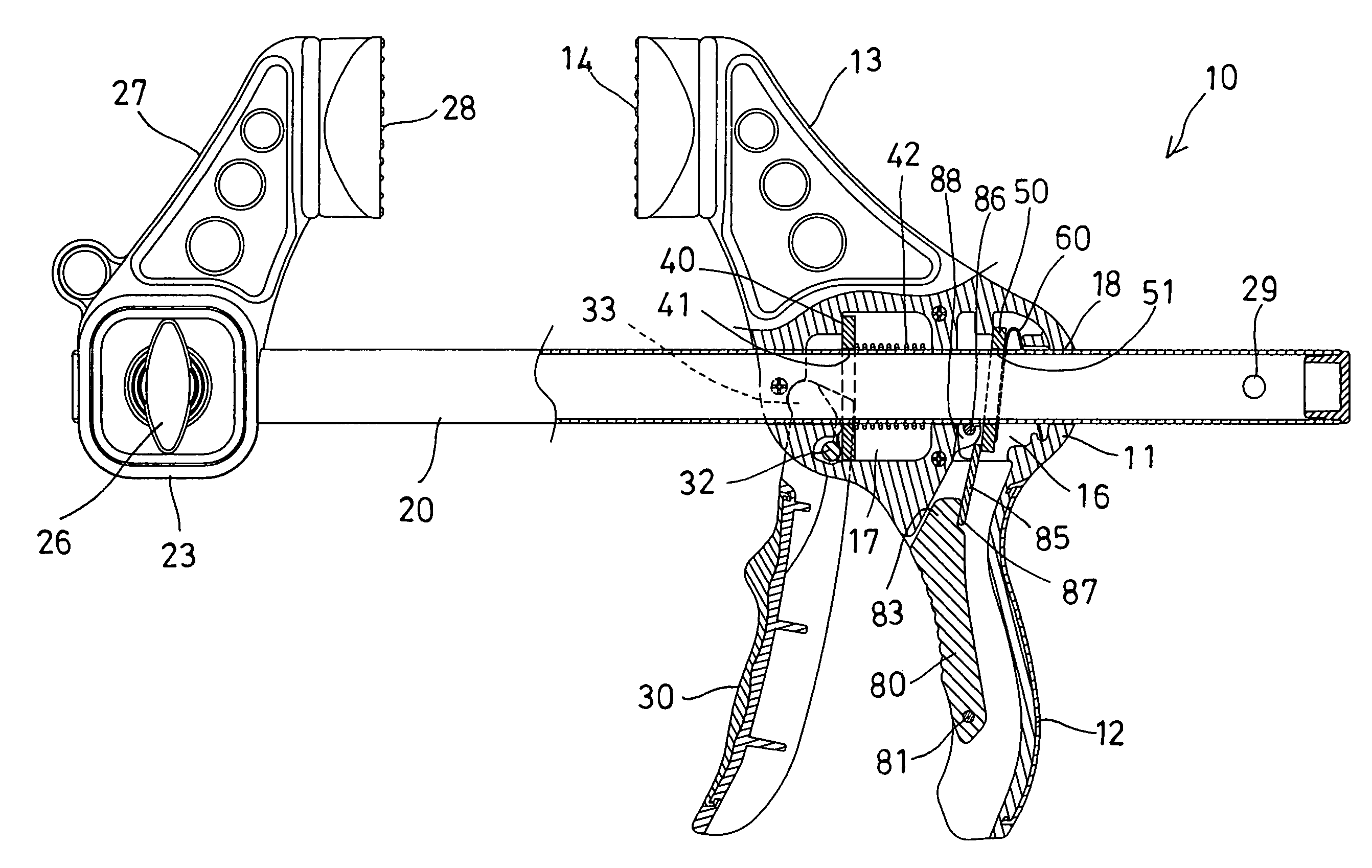
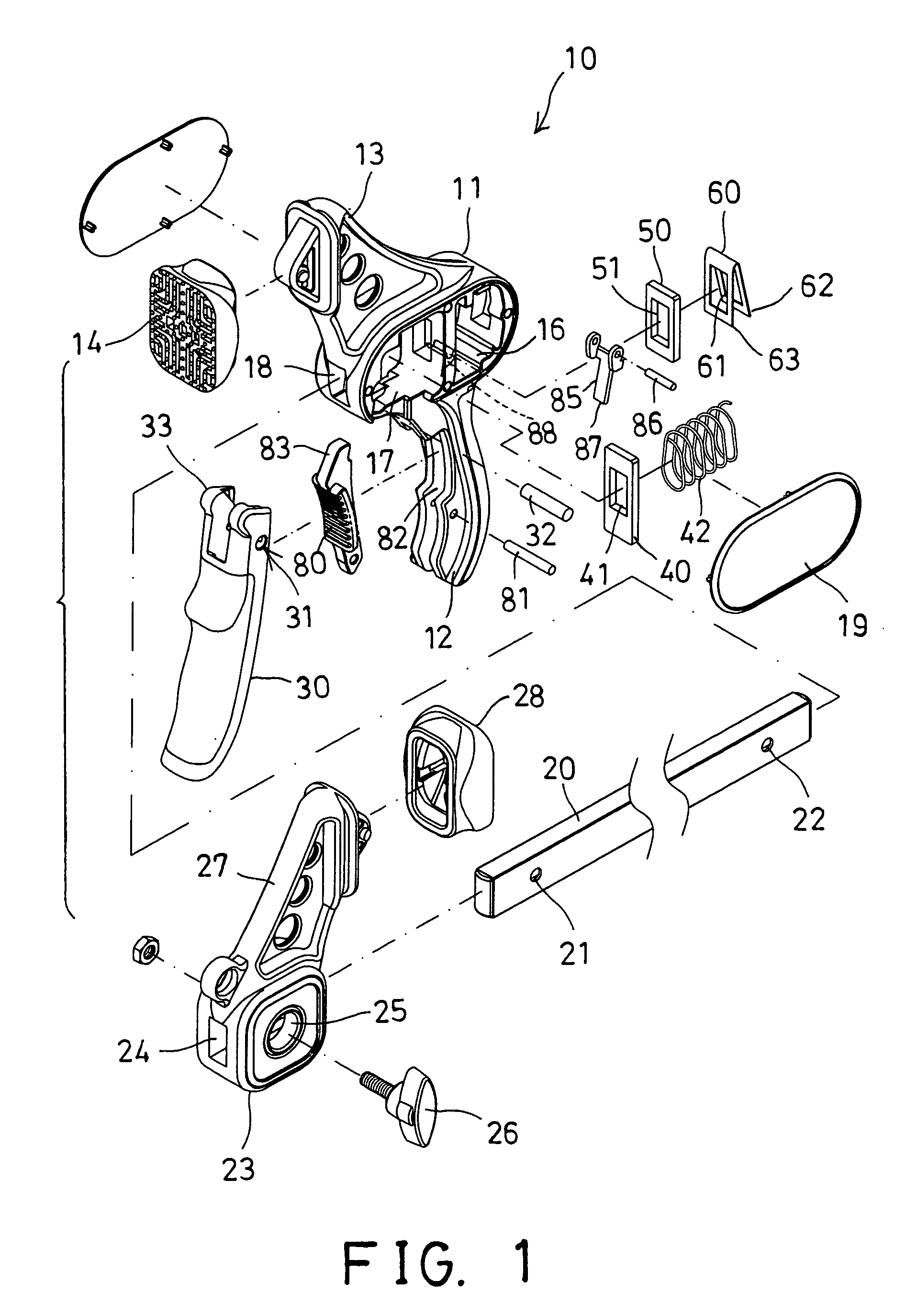
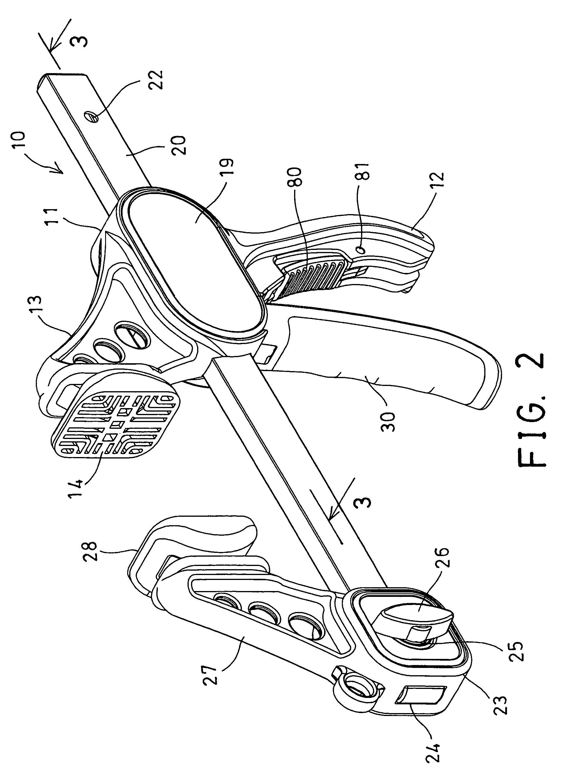
[0027]Referring to the drawings, and initially to FIGS. 1–4, a hand clamp 10 in accordance with the present invention comprises a grip body or housing 11 including a handle 12 extended downwardly therefrom for being held or grasped by the user, and a fixed jaw 13 extended from the housing 11, such as extended upwardly from the housing 11 for contacting or engaging with a work piece 90 (FIGS. 4, 6, 9), it is preferable that a soft or resilient gripping head 14 is attached to the fixed jaw 13 for softly or resiliently and safely contacting or engaging with the work piece 90.

[0028]The housing 11 includes a hollow interior, and a partition 15 disposed or engaged in the hollow interior of the housing 11 for separating the hollow interior of the housing 11 into two chambers 16, 17, such as a rear chamber 16 and a front chamber 17. The housing 11 includes a longitudinal channel 18 formed therein and formed through the partition 15 and communicating with the rear and the front chambers 16, ...


PUM


Abstract

A hand clamp includes a housing having a handle for being held by a hand of a user, a piston rod slidably received in the housing, a driving lever engaged in the housing and having an opening for slidably receiving the piston rod and biased to grip the piston rod when the driving lever is tilted relative to the piston rod. A trigger is pivotally attached to the housing and has a driving shaft for tilting the driving lever to move the piston rod step by step. A braking lever is slidably engaged on the piston rod for gripping the piston rod when the braking lever is tilted relative to the piston rod. A hand grip is pivotally coupled to the handle and has an actuating end for actuating the braking lever to release the piston rod.

Description

BACKGROUND OF THE INVENTION[0001]1. Field of the Invention[0002]The present invention relates to a hand clamp, and more particularly to a hand clamp having an auxiliary hand grip for actuating and releasing a braking lever and for allowing the hand clamp to be easily operated with a single hand of a user.[0003]2. Description of the Prior Art[0004]Various kinds of typical hand clamps or C-clamps or clamping devices have been developed and comprise a piston rod slidably received in a grip body and including a jaw member movable toward and away from a fixed jaw that is solidly attached or coupled to the grip body for selectively grasping or gripping one or more work pieces between the jaw member and the fixed jaw.[0005]For example, U.S. Pat. No. 5,217,213 to Lii discloses one of the typical quick release C-clamp including two pawls pivotally disposed in a grip and biased to engage with a rack that is slidably engaged in the grip. In operation, the user uses his one hand grasp the grip ...

Claims


Application Information

Patent Timeline
Patent Type & Authority Patents(United States)
IPC IPC(8): B25B5/02
CPCB25B5/163B25B5/068
Inventor YANG, CHUNG CHENG
Owner YANG CHUNG CHENG
Why Eureka
Try Eureka