Component dependency matrices

Inactive Publication Date: 2007-02-06
MICROSOFT TECH LICENSING LLC
View PDF6 Cites 37 Cited by
  • Summary
  • Abstract
  • Description
  • Claims
  • Application Information

AI Technical Summary

Problems solved by technology

Software developers quickly learned that this method produced inefficiencies because many different applications included large portions of fundamentally identical code.
For instance, today software is so complex that it is common to have multiple levels of references.
Over time, undesirable references can occur, such as circular referencing.
This has a negative impact on the m

Method used


Image

  • Component dependency matrices
  • Component dependency matrices
  • Component dependency matrices

Examples


Embodiment Construction

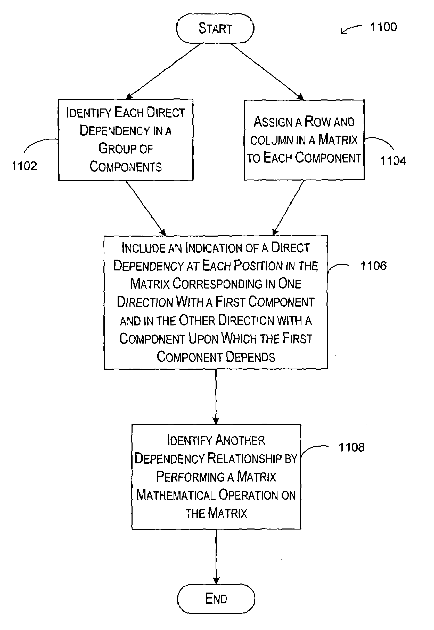
[0017]The invention provides a mechanism for identifying dependencies among software components through the use of a dependency matrix and matrix mathematics. Briefly stated, the invention involves identifying a first level of dependencies between each of a multiplicity of software components. A dependency matrix is created with each component being identified in each axis of the matrix. Thus, each component has a place in the X-axis of the matrix and a corresponding place in the Y-axis. This matrix is termed the “first order dependency” matrix.

[0018]The inventors have determined that each subsequent level of dependencies can then be computed through the application of traditional matrix mathematical principles. For instance, given the first order dependency matrix, the second order dependency matrix can be computed by simply multiplying the first order dependency matrix by itself. Higher order dependencies may be computed by multiplying the immediately prior dependency matrix by th...


PUM


Abstract

Described is a system and method for identifying dependency relationships between components in a group of software components. Given a group of software components, a set of direct dependencies between each of the components and any other component is identified. The direct dependencies are indicated in a square matrix where each component in the group of components has a corresponding row and column. A particular component has the same row number as column number in the matrix. Multiplying that the matrix by itself identifies second-order dependencies. Higher order dependencies are identified by repeating the multiplication of the resultant matrix by the first-order dependency matrix. In other words, multiplying the third-order matrix by the first-order matrix achieves the fourth-order matrix, and so on.

Description

FIELD OF THE INVENTION [0001]The present invention relates to software design. More particularly, the present invention relates to tools for identifying component dependencies.BACKGROUND OF THE INVENTION[0002]When software programming was in its early stages, a software application was commonly created as one large binary file. In other words, the result of compiling a software application was a single executable file. Software developers quickly learned that this method produced inefficiencies because many different applications included large portions of fundamentally identical code. From that issue evolved dynamic linking. With dynamic linking, a software application is written in two or more pieces. The code in one piece may refer to code in another piece. When the application is compiled, a separate component of binary code is created for each piece of the application. When the application is launched, the pieces are linked together in memory to form the entire application.[000...

Claims


Application Information

Patent Timeline
IPC IPC(8): G06F9/44
CPCG06F8/71
Inventor ONDRUSEK, BOHUSSANTOS, PATRICK JOSEPH DINIOBURROWS, KEVIN WARD
Owner MICROSOFT TECH LICENSING LLC
Why Eureka
Try Eureka