Displaceable support stand

a support stand and displaceable technology, applied in the field of displaceable support stands, can solve the problems of cable damage or squashing by the wheels, affecting the stability the difficulty of fine positioning of the support stand, so as to reduce the risk of injury, enhance the freedom of movement, and stabilize the air pressure of the air cushion

Active Publication Date: 2007-02-13
CARL-ZEISS-STIFTUNG TRADING AS CARL ZEISS
View PDF16 Cites 14 Cited by
  • Summary
  • Abstract
  • Description
  • Claims
  • Application Information

AI Technical Summary

Benefits of technology

[0017]In order to stabilise the air pressure of the air cushion, a flexible skirt can be provided around the support stand base. The skirt serves at the same time to push aside or fend off cables or other objects. In particular that also makes it possible to reduce the risk of injury to the operating personnel, even with an air cushion lift height which is greater than about 12–20 mm.
[0018]The support stand according to the invention can be provided with a hose-connected compressed air supply. That means that the radius of movement of the support stand is admittedly limited to regions in which a compressed air supply i

Problems solved by technology

Support stands of that kind however are relatively difficult to manoeuvre within tight spaces, in particular if relatively high forces have to be applied by the operating personnel in the manoeuvring procedure, because the support stand is of great weight.
Fine positioning of the support stand can therefore be difficult.
In that case there is the danger of the cables being damaged or squashed by the wheels,

Method used


Image

  • Displaceable support stand
  • Displaceable support stand
  • Displaceable support stand

Examples


Embodiment Construction

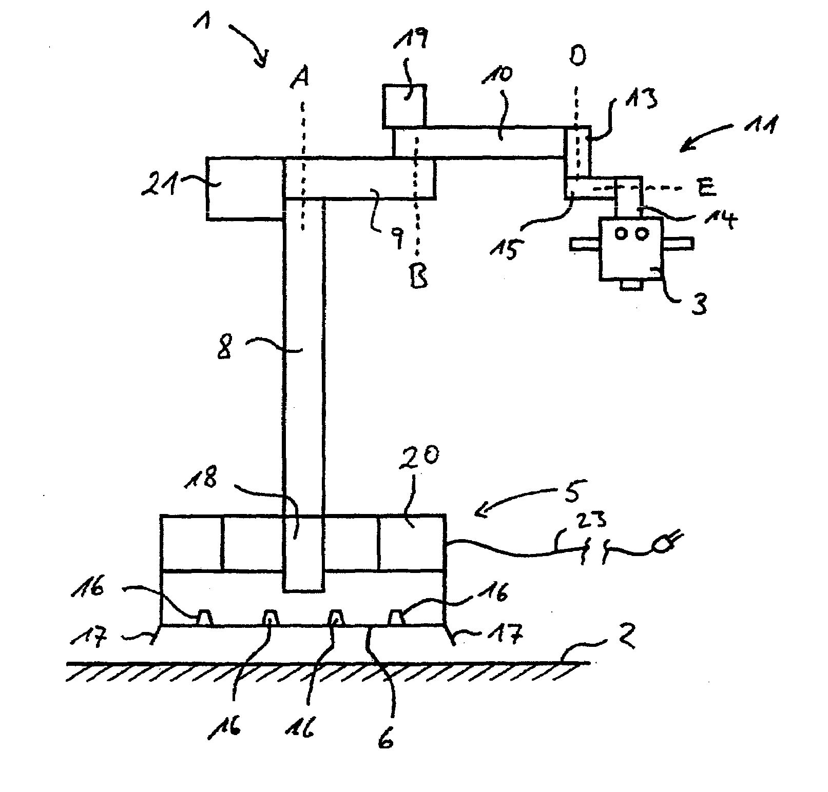
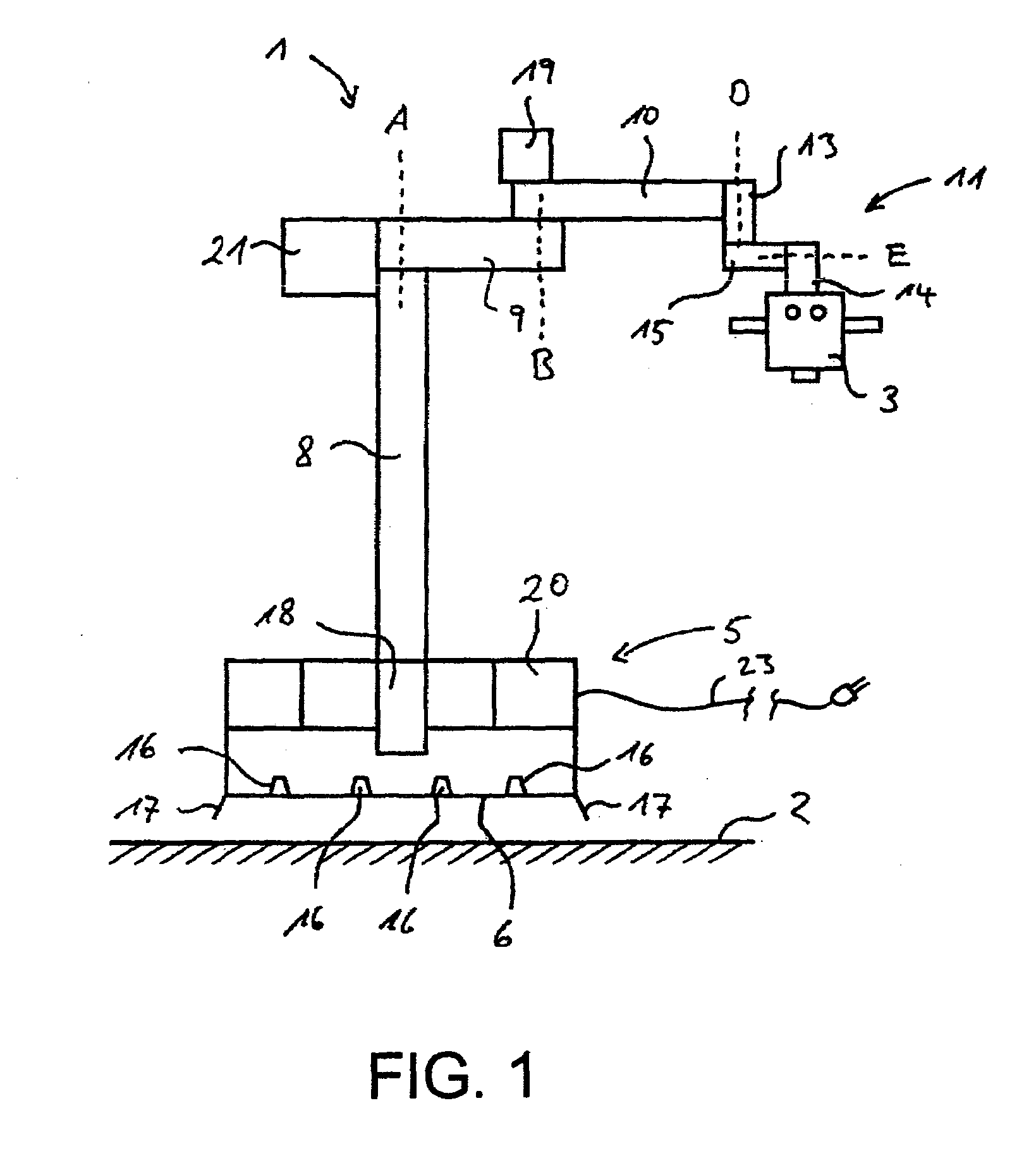
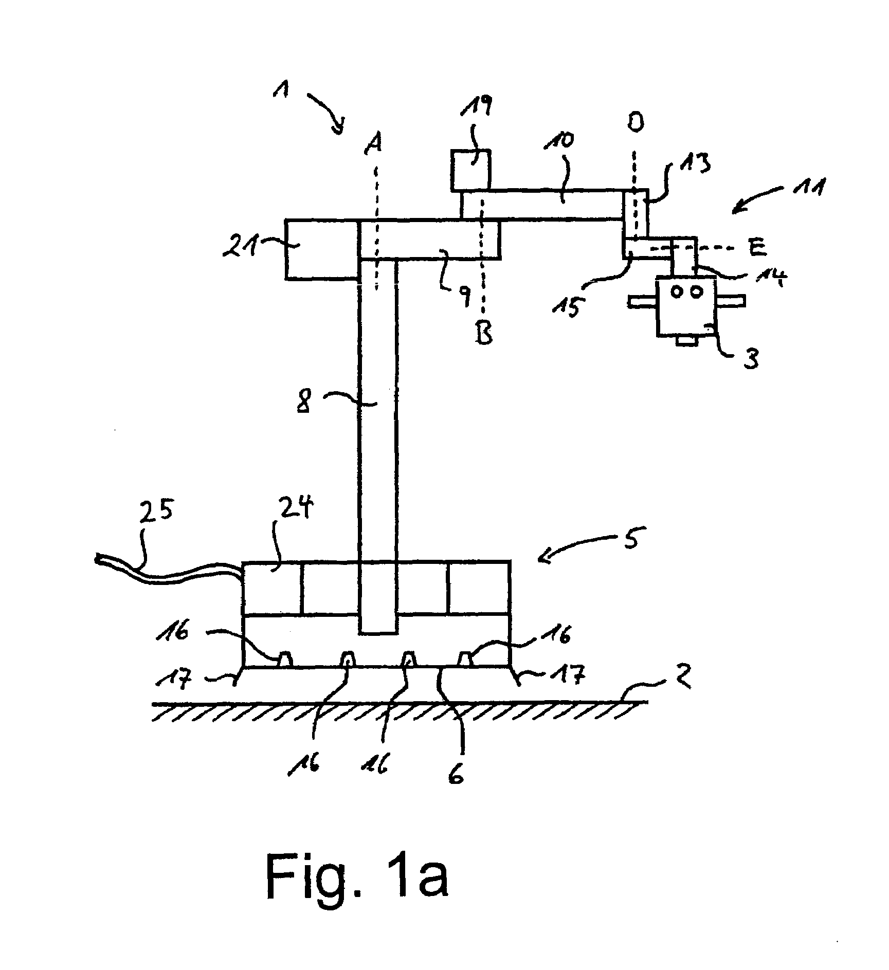
[0032]A support stand 1 according to the invention with a microscope 3 secured thereto, which in the illustrated embodiment is an surgical microscope, is diagrammatically shown in FIG. 1. The support stand base 5 of the support stand 1 is shown in section.

[0033]The support stand 1, as support stand components, includes a height-adjustable support stand column 8, a carrier arm 9, a spring arm 10 and a microscope suspension assembly 11 which in turn includes a connecting element 13, a pivot arm 15 and a holding arm 14. At its one end the carrier arm 9 is connected to the support stand column 8 rotatably about an axis A. An end of the spring arm 10 is mounted to the other end of the carrier arm 9 rotatably about an axis B which is parallel to the axis A so that the carrier arm 9 and the spring arm 10 form a hinge arm. The other end of the spring arm 10 is formed by a tilting mechanism (not shown) to which the microscope suspension assembly 11 is fixed and which permits a tilting moveme...


PUM


Abstract

A displaceable support stand (1) includes a support stand base (5) with a support surface (6) which is adapted to rest on the ground, a lifting device for lifting the support stand base (5) and therewith the support stand (1) above the ground and a displacement device which permits displacement of the support stand (1). The lifting and the displacement devices can be embodied by a device for producing an air cushion. A device of that kind can include for example a compressor (18), an accumulator (20) for the power supply for the compressor (18) and air nozzles (16).

Description

BACKGROUND OF THE INVENTION[0001]1. Field of the Invention[0002]The present invention concerns a displaceable support stand and in particular a displaceable support stand for optical viewing devices, for example surgical microscopes.[0003]2. Description of the Related Art[0004]A typical support stand as is used in particular for surgical microscopes is displaced by means of caster wheels, as are also known for example from hospital beds. When the support stand has reached its final position, further movement is prevented by actuation of a locking brake. Usually the locking brake acts directly on the caster wheels or, in the form of lowerable feet, directly on the floor on which the support stand is supported. A support stand of that kind is described for example in WO 98 / 53244. The support stand described therein includes a support stand base which has caster wheels and lowerable support feet. The support feet are lowered in the working position of the support stand while, for displ...

Claims


Application Information

Patent Timeline
IPC IPC(8): B60V1/04A61B19/00F16M11/42G02B7/00
CPCA61B19/26F16M11/42G02B7/001F21L14/04F16M11/10F16M11/18F21V21/06A61B19/5223F16M2200/068F21W2131/20F16M2200/04A61B90/20A61B90/25A61B90/50
Inventor KRAUS, MARTIN
Owner CARL-ZEISS-STIFTUNG TRADING AS CARL ZEISS
Why Eureka
Try Eureka