Eureka AIR delivers breakthrough ideas for toughest innovation challenges, trusted by R&D personnel around the world.

Memory disk shipping container with improved contaminant control

Inactive Publication Date: 2007-02-13
MAXTOR
View PDF98 Cites 12 Cited by
  • Summary
  • Abstract
  • Description
  • Claims
  • Application Information

AI Technical Summary

Benefits of technology

[0011]An advantage and feature of the various embodiments of the present invention is that the top cover is sealed and latched to the cassette without a snap action that can generate and launch particles onto the contents of the cassette, while not requiring any affirmative locking action by the user other than pressing the cover onto the cassette. In addition, due to the mechanical advantage caused by the placement of the latch engagements, the top cover can be more easily unlatched than snap-on top covers or other conventional covers.

Problems solved by technology

In the preferred embodiment, the U-shaped locking member is integrally formed with the top portion of the top cover and has limited flexibility allowing it to distort slightly as part of the locking process.

Method used


Image

  • Memory disk shipping container with improved contaminant control
  • Memory disk shipping container with improved contaminant control
  • Memory disk shipping container with improved contaminant control

Examples


first embodiment

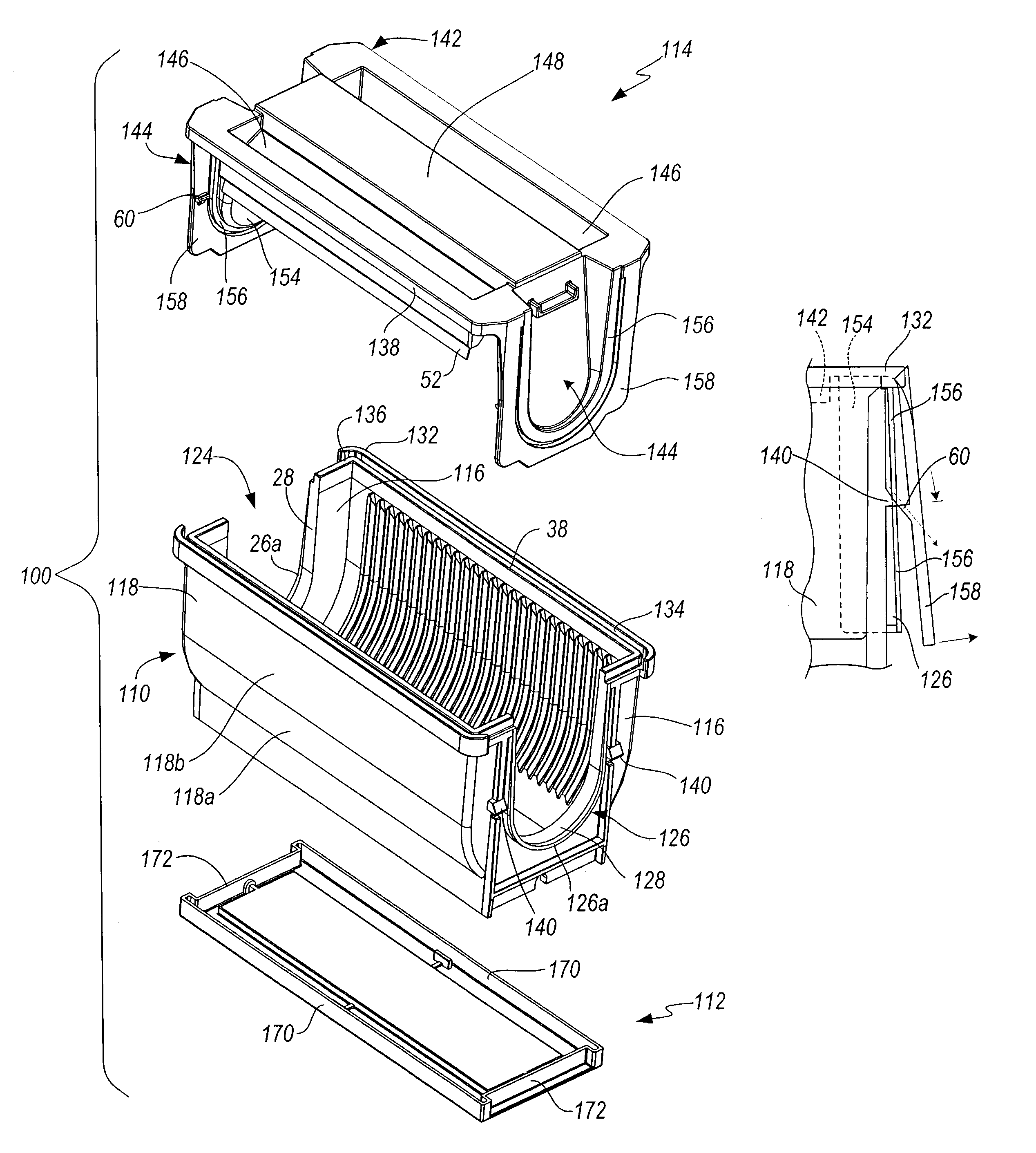
[0050]Referring first to FIG. 9, the invention is shown in the context of a shipping and storage container for memory disks generally designated with the numeral 100. When used alone herein, “disk” should be considered as any type of memory disk, including both magnetic and optical memory disks. In general terms and with reference to the drawings, the disk shipper is comprised of three pieces: a base or cassette 110 having an open top, open bottom and open ends; a bottom cover 112 for enclosing the open bottom of the cassette and, a top cover 114 for enclosing the open top and open ends of the cassette. The cassette, as illustrated in more detail in FIGS. 10–17, has two end walls 116 and two parallel side walls 118 extending between the end walls. Slots 120 are formed in the side walls of the cassette by inwardly extending teeth or ribs 122. The slots are configured to hold magnetic disks in parallel axial alignment by engaging the outer edge portions of the disks. The side walls 11...

second embodiment

[0056]the present invention is shown in FIGS. 24–31. In this embodiment, the base or cassette 202 and the top cover 204 remain generally the same. However, the latching mechanism is different. Turning to the cassette 202, and more particularly, the end walls 206, a pair of cutout portions 208 and 210 are formed on the underneath surface of the lower portion of the saddle 212 to create a ridge or lip 214 (see FIG. 25). The lip 214 cooperates with a locking member associated with the top cover to secure the cover to the cassette.

[0057]As shown in FIGS. 24, 26, 27 and 29, the top cover 204 includes a locking member 216 pivotally attached to the top cover 204 by a hinge 218. The hinge 218 permits the locking member 216 to pivot relative to the top cover while, simultaneously, the U-shaped structural offset 220 is sealably nested within the saddle 212 when the top cover 204 is properly seated on the cassette 202. This allows the locking member 216 to pivot upwardly and downwardly about t...


PUM


Abstract

A container for disks has an improved latching mechanism. The container comprises a cassette with sidewalls with slots for holding disks in an axial arrangement, two opposite end walls each have a U-shaped recess extending downwardly from the open top, a top cover with a rectangular top portion and two end portions extend downwardly to cover the U-shaped recess. The top cover latches to the cassette by way of a latching mechanism which includes a living hinge, an extension portion, and a hook portion all on each end portion. The hook portion cooperates and engages with a cooperative catch member on the cassette. The extension member is under tension to secure the top cover in place. In an alternate embodiment, recesses on the extension portion connect to nubs on the cassettes or on the bottom cover to secure the top cover in place.

Description

CROSS-REFERENCE TO RELATED APPLICATIONS[0001]Priority is claimed from U.S. Provisional Patent Application Ser. Nos. 60 / 377,876 filed May 3, 2002 and 60 / 403,819 filed Aug. 14, 2002, which are incorporated by reference herein in their entirety.FIELD OF THE INVENTION[0002]This invention relates to containers for storing and transporting memory storage disks, such as magnetic and optical disks. More particularly it relates to such a container with an improved latching mechanism and one with a more robust design.BACKGROUND OF THE INVENTION[0003]Storage disks are utilized in the computer industry, as well as other ever-expanding applications, for storage of information. Storage disks may be made of metal or glass and are subjected to a number of processing steps. Such storage disks must be transported, not only within the place of manufacturing during processing, but from the processing and manufacturing facilities to the manufacturing facility where the disks are placed in end use device...

Claims


Application Information

Patent Timeline
IPC IPC(8): B65D85/00A45C13/10B65D77/26B65D85/57G11B33/04
CPCG11B33/0444Y10S206/832
Inventor HACHTMANN, BRUCE
Owner MAXTOR
Why Eureka
Eureka Blog
Learn More