Eureka AIR delivers breakthrough ideas for toughest innovation challenges, trusted by R&D personnel around the world.

Hook device

a technology of a hook and a handle, which is applied in the direction of building locks, constructions, fastening means, etc., can solve the problems of affecting the appearance of the device, user accidental injury, and limited aesthetics of the device, so as to achieve the effect of not reducing the convenience of us

Active Publication Date: 2008-07-15
ASUSTEK COMPUTER INC
View PDF4 Cites 2 Cited by
  • Summary
  • Abstract
  • Description
  • Claims
  • Application Information

AI Technical Summary

Benefits of technology

[0005]Therefore, one objective of the present invention is to provide a hook device, in which a movable slider and a movable hook are used, wherein when the hook is not in operation, the hook can be hidden within a hook base such that the original design model will not be affected, the usage convenience will not be reduced, and the user will not be injured.
[0006]Another objective of the present invention is to provide a hook device, which has advantages of a great connection force and an unlimited connection depth and still be easily latched and unlatched, so that the hook device is very convenient to use.

Problems solved by technology

However, a hook of this design impairs the device appearance, and because the hook tip 104 of the exposed connection portion 108 is sharp-pointed, the user might be accidentally injured by the hook tip 104.
Thus, the aesthetics of the device is limited and the comfort of use is reduced.

Method used


Image

  • Hook device
  • Hook device
  • Hook device

Examples


Embodiment Construction

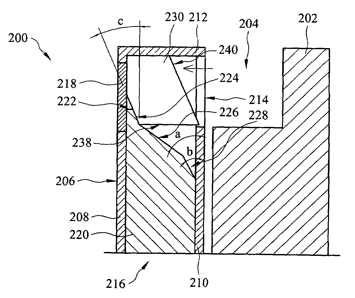
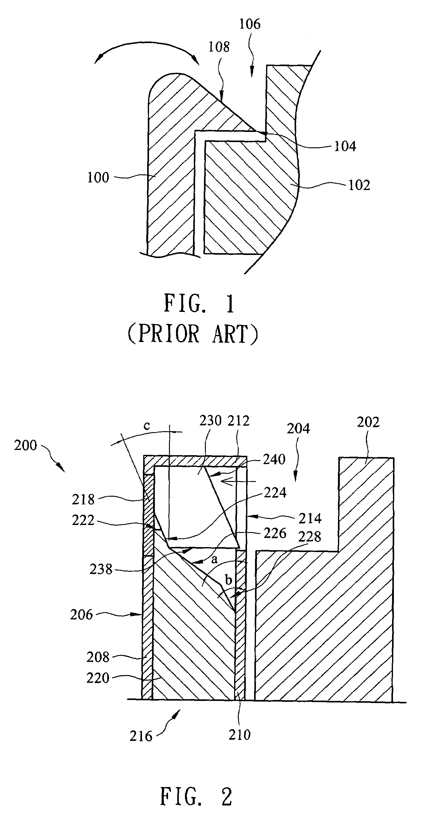
[0014]The present invention discloses a hook device having a hidden hook, which can increase the flexibility of the device aesthetics and can enhance the convenience and the safety in the use of the hook. In order to make the illustration of the present invention more explicit and complete, the following description is stated with reference to FIGS. 2 and 3.

[0015]FIG. 2 is a schematic diagram of a hook device in accordance with a preferred embodiment of the present invention, wherein the hook is not in operation and is at an original position. The hook device 200 is mainly composed of a hook base 206, an attractive member 218, a slider 220 and a hook 230. The hook base 206 is mainly composed of a top plate 212, and a sidewall 210 and a sidewall 208 on opposite sides, in which the sidewall 210 and the sidewall 208 are respectively joined to two sides of the top plate 212 to form a containing chamber 216. The sidewall 210 of the hook base 206 includes an opening 214 adjacent to the to...


PUM


Abstract

A hook device includes a hook base, an attractive member, a slider and a hook. The hook base includes a containing chamber, in which the containing chamber has an opening. The attractive member is set in a sidewall of the containing chamber and is opposite to the opening. The slider is disposed within the containing chamber, in which the slider has a top surface. The hook is disposed in the containing chamber and is on the top surface of the slider, in which a magnetic attractive power is induced between the hook and the attractive member. The hook may further include a secondary hook base having a hook groove corresponding to the opening. A portion of the hook is removed out through the opening of the containing chamber and is clipped in the hook groove by pushing the slider.

Description

RELATED APPLICATIONS[0001]The present application is based on, and claims priority from, Taiwan Application Serial Number 94124408, filed Jul. 19, 2005, the disclosure of which is hereby incorporated by reference herein in its entirety.FIELD OF THE INVENTION[0002]The present invention relates to a hook device, and more particularly, to a hidden hook device.BACKGROUND OF THE INVENTION[0003]FIG. 1 is a schematic diagram of a typical hook device, in which a hook 100 is usually exposed on the exterior of the device, and a hook tip 104 is usually sharp-pointed. When the hook 100 is put into a corresponding hook base 102, the exposed hook 100 is pressed into a hook rabbet 106 of the hook base 102, to make a connection portion 108 of the hook 100 lodge in the hook rabbet 106, so that the whole device can be joined with the hook base 102 by the hook 100, such as shown in FIG. 1. The hook 100 can be separated from the hook base 102 by removing the hook 100 from the hook rabbet 106 of the hoo...

Claims


Application Information

Patent Timeline
Patent Type & Authority Patents(United States)
IPC IPC(8): E05C17/56
CPCE05B47/004E05C1/06Y10T292/0976Y10T292/11
Inventor CHEN, CHENG-CHU
Owner ASUSTEK COMPUTER INC
Why Eureka
Eureka Blog
Learn More