
Vehicle spoiler with spinner mechanism

a technology of air flow control and vehicle, which is applied in the direction of roofs, vehicle arrangements, transportation and packaging, etc., can solve the problems of reducing the speed of the vehicle, and reducing the air flow drag on the vehicle. , to achieve the effect of reducing the air flow drag and reducing the effect of surface dust accumulation

Inactive Publication Date: 2007-02-13
GARCIA MARTIN LEE
View PDF8 Cites 23 Cited by
  • Summary
  • Abstract
  • Description
  • Claims
  • Application Information

AI Technical Summary

Benefits of technology

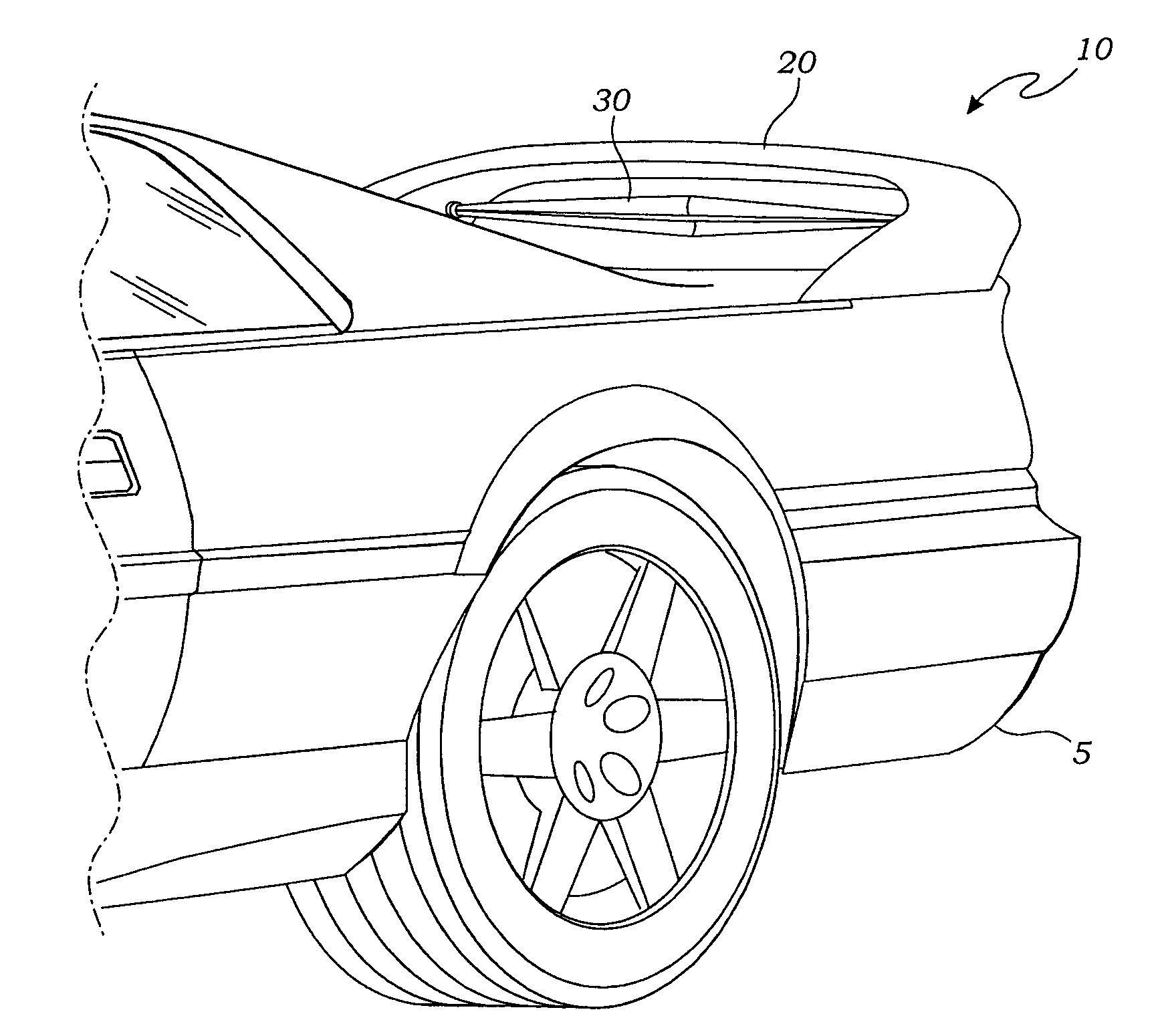
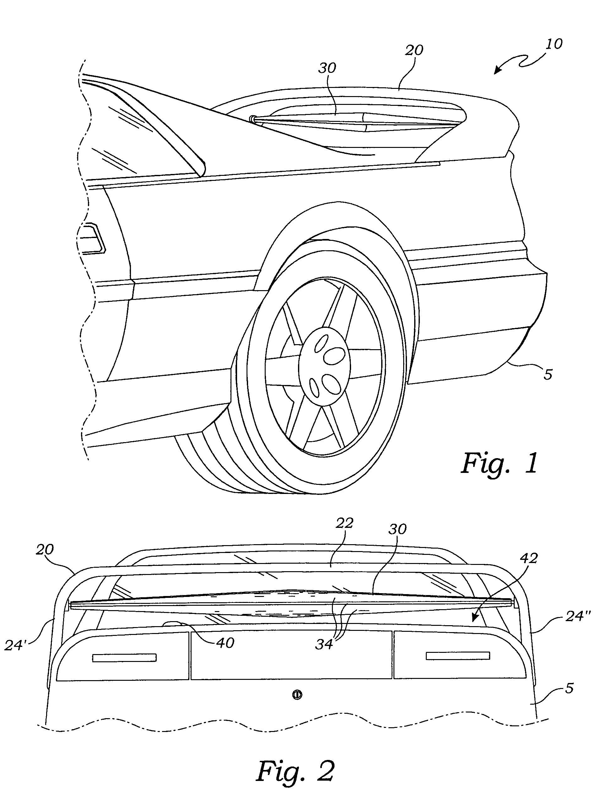
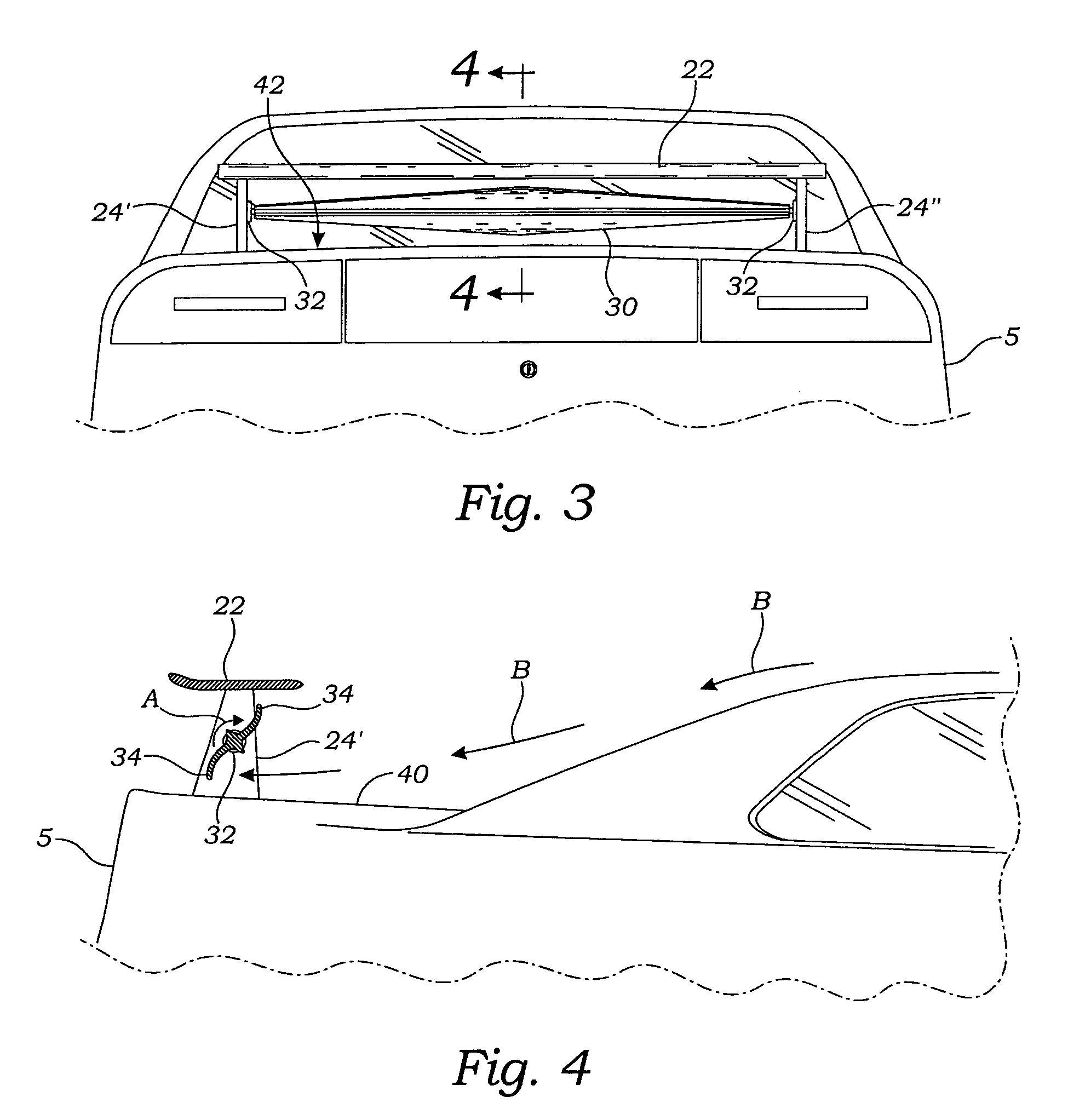
[0012]It is well known in the automotive world, and especially in automotive racing, that the surface sticking effect of air as it flows over a vehicle's surface produces considerable drag. When the air flow is laminar or smooth-moving, it produces drag by two effects on a typical automobile; first by the surface sticking effect and second by generating a low pressure rearward of the top or canopy of the vehicle. This low pressure tends to retard the vehicle's forward movement. Both of these drag effects can be reduced and ultimately eliminated by causing the air nearest the vehicle's surface to move with a more turbulent manner. The presently described apparatus is a mechanism for producing turbulent flow of the air moving over the rear deck of a vehicle. It is an air flow control apparatus comprising a vehicle spoiler of a typical and well known type having a horizontal portion joined integrally with spaced apart vertical standoffs. Mounted between the standoffs is a rotating spinner held in bearing sets. The spinner provides blades configured for rotating the spinner when the vehicle moves.
[0015]A further objective is to provide such an apparatus that reduces air flow drag on vehicle.
[0016]A still further objective is to provide such an apparatus that reduces a surface dust accumulation effect on a rear desk of a moving vehicle.

Problems solved by technology

It is well known in the automotive world, and especially in automotive racing, that the surface sticking effect of air as it flows over a vehicle's surface produces considerable drag.
This low pressure tends to retard the vehicle's forward movement.

Method used


Image

  • Vehicle spoiler with spinner mechanism
  • Vehicle spoiler with spinner mechanism
  • Vehicle spoiler with spinner mechanism

Examples


Embodiment Construction

[0023]The above described drawing figures illustrate the described apparatus and its method of use in at least one of its preferred, best mode embodiment, which is further defined in detail in the following description. Those having ordinary skill in the art may be able to make alterations and modifications what is described herein without departing from its spirit and scope. Therefore, it must be understood that what is illustrated is set forth only for the purposes of example and that it should not be taken as a limitation in the scope of the present apparatus and method of use.

[0024]Described now in detail is an air flow control apparatus 10 as best seen in FIG. 1. The apparatus, preferably made of plastic or metal, includes a vehicle spoiler 20 providing a horizontal portion 22 joined integrally with spaced apart vertical standoffs 24′ and 24″. Such spoilers 20 are well known in the art. In the present apparatus, the spoiler 20 preferably comprises a horizontal plate with a trai...


PUM


Abstract

A mechanism for producing turbulent flow of the air moving over the rear deck of a vehicle is an air flow control apparatus comprising a vehicle spoiler of a typical and well known type having a horizontal portion joined integrally with spaced apart vertical standoffs. Mounted between the standoffs is a rotating spinner held in bearing sets. The spinner provides blades configured for rotating the spinner when the vehicle moves using its slipstream.

Description

CROSS-REFERENCE TO RELATED APPLICATIONS[0001]This is a continuation-in-part application of U.S. Design Patent application Ser. No. 29 / 230,466, filed May 20, 2005 and which is incorporated herein by reference.STATEMENT REGARDING FEDERALLY SPONSORED RESEARCH OR DEVELOPMENT[0002]Not applicable.THE NAMES OF THE PARTIES TO A JOINT RESEARCH AGREEMENT[0003]Not applicable.INCORPORATION-BY-REFERENCE OF MATERIAL SUBMITTTED ON A COMPACT DISC[0004]Not applicable.REFERENCE TO A “MICROFICHE APPENDIX”[0005]Not applicable.BACKGROUND OF THE INVENTION[0006]1. Field of the Present Disclosure[0007]This disclosure relates generally to devices for controlling the flow of air over a vehicle and more particularly to a spinning device used in conjunction with an air spoiler enabled for producing eddies over the rear surface of a vehicle in order to reduce air stiction drag and to limit dust buildup.[0008]2. Description of Related Art Including Information Disclosed Under 37 CFR 1.97 and 1.98[0009]Brouch, et...

Claims


Application Information

Patent Timeline
Patent Type & Authority Patents(United States)
IPC IPC(8): B60J1/00
CPCB62D35/007Y02T10/82
Inventor GARCIA, MARTIN LEE
Owner GARCIA MARTIN LEE
Learn More