Electrical connector with a spring push button for disengagement with jack

a technology of electric connectors and push buttons, applied in the direction of electrical apparatus, connection, coupling device connection, etc., can solve the problems of wear of hooks and other associated components, the disengagement of connector components, and the need for great for

Inactive Publication Date: 2007-02-13
ADVANCED CONNECTEK INC
View PDF14 Cites 135 Cited by
  • Summary
  • Abstract
  • Description
  • Claims
  • Application Information

AI Technical Summary

Benefits of technology

[0007]An object of the present invention is to provide an electrical connector including a jack having two internal opening, and a plug comprising a top shell comprising a third opening; a spring biased push button slidably anchored in the third opening and comprising an indentation at either side, and a front trigger adjacent the indentation; two positioning devices each comprising a front first protrusion at one end, a rear U-shaped positioning member, and an intermediate second protrusion; a shield case comprising a front sheath having two side first openings, an intermediate peripheral flange, two side first slits in a rear; an insulative body including a forward extension including two side flats, a front projected plate, and a plurality of lengthwise T-shaped first apertures arranged in upper and lower rows wherein the extension is fitted in the sheath; a rear U-shaped frame element including two inner recessed portions on both sides, and two rear sidewalls each including a lengthwise U-shaped second slit extended toward the flat wherein each positioning device is inserted through the second slit with the first protrusion passed the second slit and the flat to project from the first opening, and upper and lower grooves; a plurality of conductors tightly inserted into the first apertures; a grounding plate including two hooks extended forward from both sides; upper and

Problems solved by technology

Otherwise, a normal plugging or unplugging of the electrical connector may break cable or cause a disengagement of the connector components.
However, the abo

Method used


Image

  • Electrical connector with a spring push button for disengagement with jack
  • Electrical connector with a spring push button for disengagement with jack
  • Electrical connector with a spring push button for disengagement with jack

Examples


Embodiment Construction

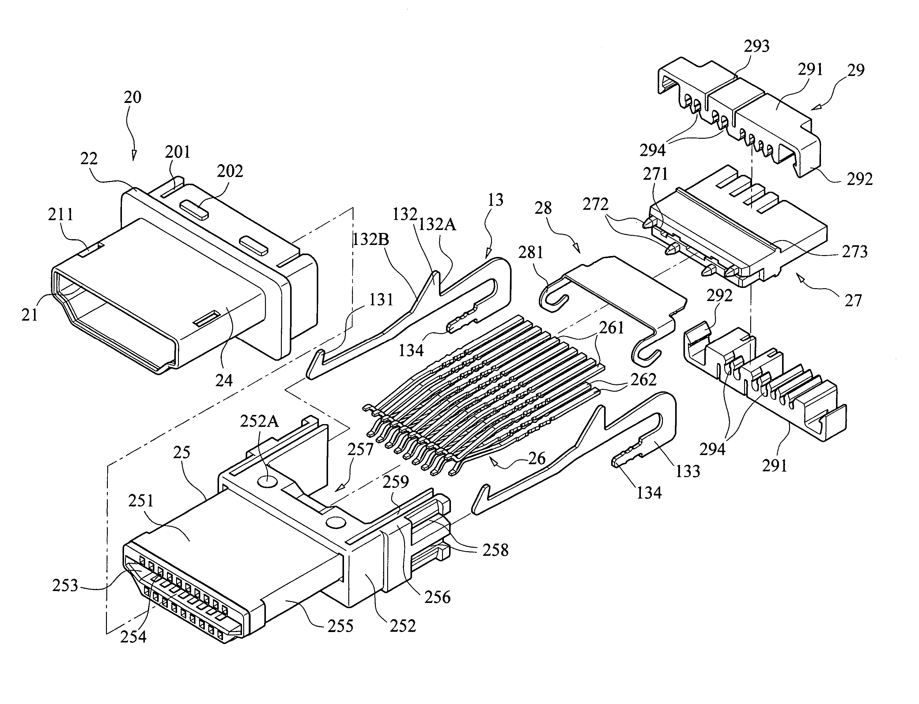
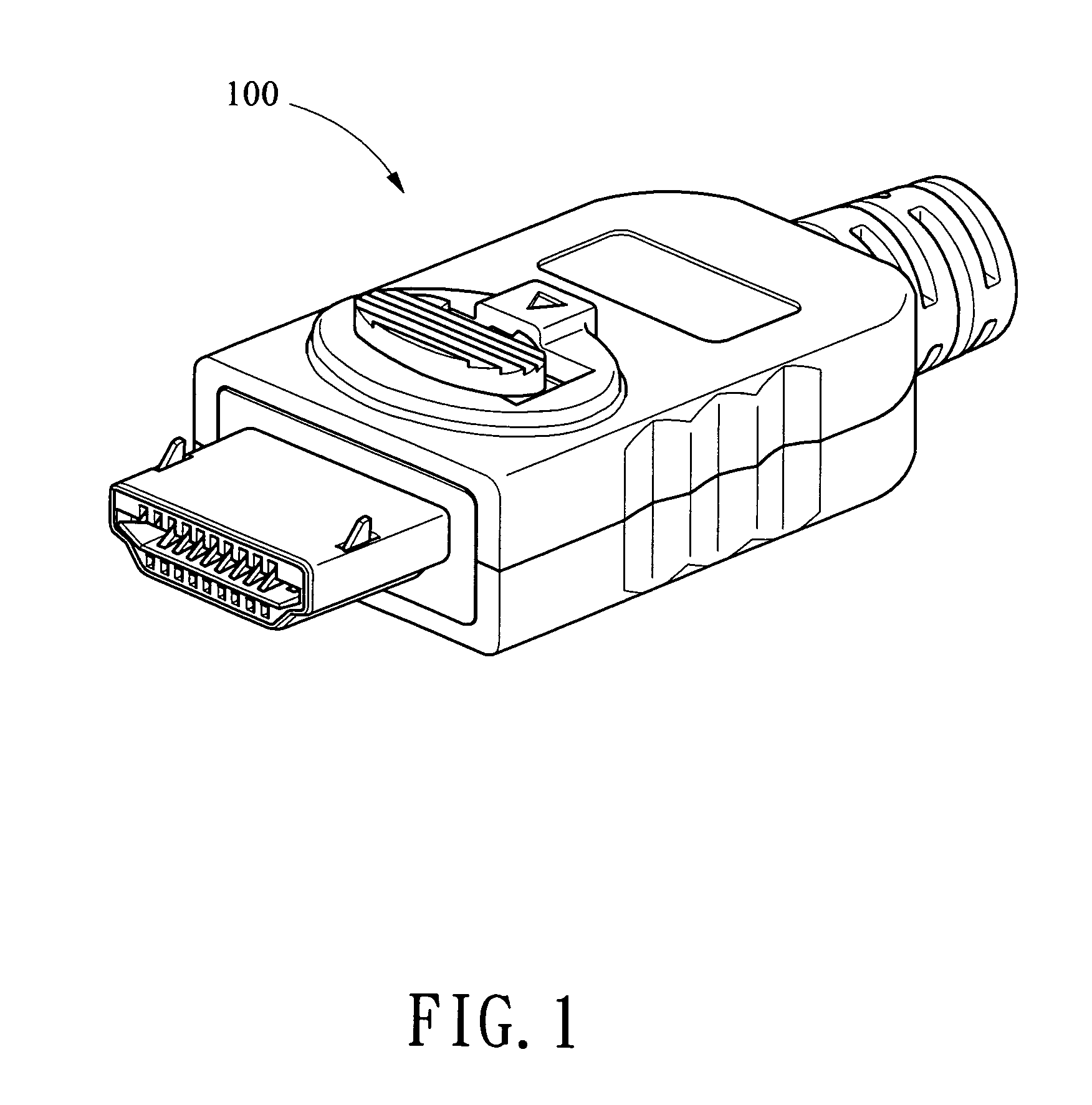
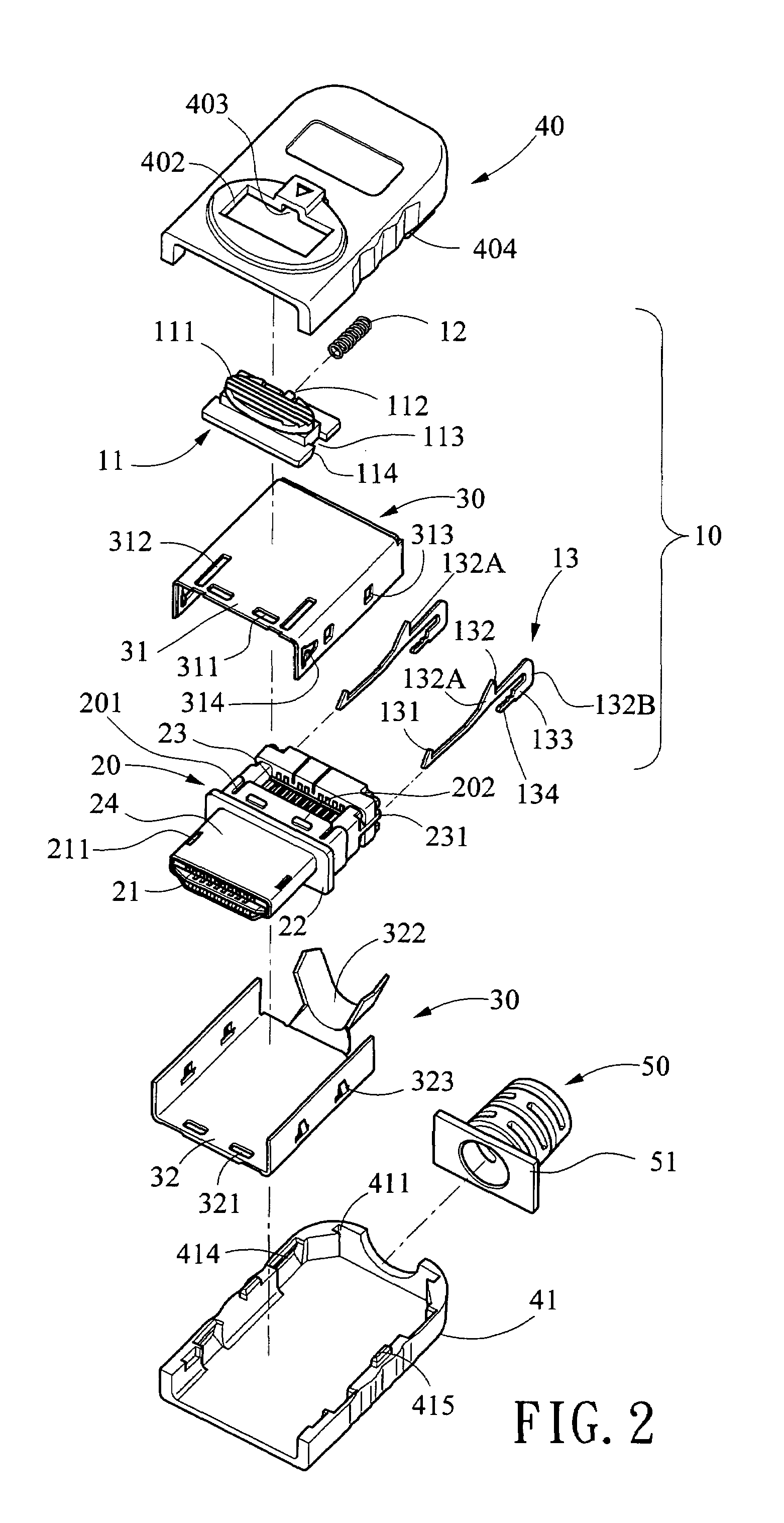
[0022]Referring to FIGS. 1 to 6, an electrical connector 100 of the invention comprises a jack (not shown) and a plug including a sliding unit 10, a shield case 20, a metal casing 30, a top shell 40, a bottom shell 41, and a strain relief 50. Each component is discussed in detailed below. The sliding unit 10 is comprised of a rectangular slide member 11 including a top push button 111, a rear bar-shaped projection 112, and an indentation 113 at either side, a front trigger 114 having two inclined surfaces each adjacent a forward end of the indentation 113, a compression spring 12, and two elongated positioning devices 13 each including a front first protrusion 131 at one end, a rear U-shaped positioning member 133 having teeth 134, and an intermediate second protrusion 132 having a rear shoulder 132A and a forward slope 132B.

[0023]The shield case 20 comprises a front projected sheath 24 having a lengthwise channel 21 and two side first openings 211, an intermediate peripheral flange...


PUM


Abstract

An electrical connector including a jack and a plug is disclosed. The plug includes a spring biased push button slidably anchored in an opening on a top shell and including an indentation at either side, and a front trigger adjacent the indentation; two U-shaped positioning devices each comprising a front first protrusion at one end and an intermediate second protrusion; and a shield case comprising a grounding plate. The push button is pushed forward to engage with a front end of the opening in an inoperative state. The push button is adapted to push rearward to cause the trigger to push and press down the second protrusions until the first protrusions clear internal openings of the jack such that a subsequent pulling will disengage the plug with the jack.

Description

[0001]This is a continuation-in-part of U.S. patent application Ser. No. 11 / 211,522, filed on Aug. 26, 2005 in the name of Wen-Hsien Tsai and entitled “LATCHING STRUCTURE OF A CONNECTER” is now pending.BACKGROUND OF THE INVENTION[0002]1. Field of the Invention[0003]The present invention relates to electrical connectors, and more particularly to such an electrical connector having a spring biased push button adapted to push in a direction away from a fastened jack for disengagement therewith.[0004]2. Description of Related Art[0005]With the progress of technology, more advanced electronic products are available in a faster pace. Also, the development of transmission interfaces is significant in recent years. For example, universal serial bus (USB), digital video interface (DVI), high definition multimedia interface (HDMI), etc. are some well known ones. Electrical connectors compatible with these interfaces are also developed constantly. In addition to the transmission speed, the for...

Claims


Application Information

Patent Timeline
IPC IPC(8): H01R13/627
CPCH01R13/6275H01R13/6585H01R13/6582
Inventor TSAI, WEN-HSIEN
Owner ADVANCED CONNECTEK INC
Why Eureka
Try Eureka