Stent design having stent segments which uncouple upon deployment

a technology of stent segments and anvils, applied in the field of stents, can solve problems such as open gaps between unconnected tips or loops

Active Publication Date: 2007-02-13
CARDINAL HEALTH SWITZERLAND 515 GMBH
View PDF24 Cites 304 Cited by
  • Summary
  • Abstract
  • Description
  • Claims
  • Application Information

AI Technical Summary

Benefits of technology

[0019]The present invention overcomes the disadvantages associated with undesirable loading effects during stent loading and stent deployment as briefly discussed above. The present invention also overcomes many of the disadvantages associated with reduced radiopacity exhibited by self-expanding stents, balloon-expandable stents, and other medical devices as briefly discussed above. In addition, the present invention also overcomes the disadvantages associated with the potential loading effects caused by the interconnectedness of the structural members.

Problems solved by technology

When bridges are periodically spaced, open gaps may exist between unconnected tips or loops.

Method used


Image

  • Stent design having stent segments which uncouple upon deployment
  • Stent design having stent segments which uncouple upon deployment
  • Stent design having stent segments which uncouple upon deployment

Examples


Embodiment Construction

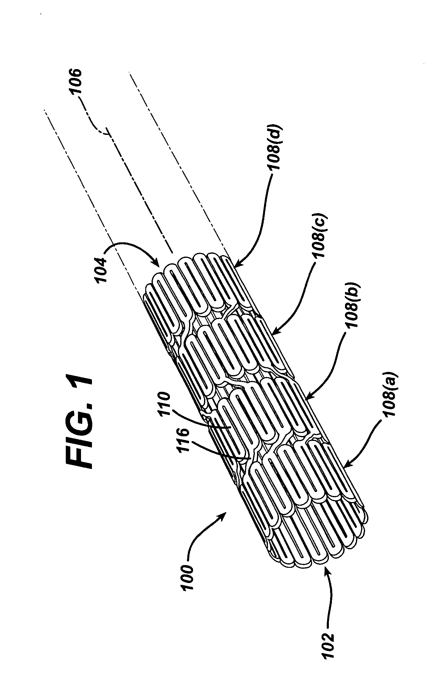
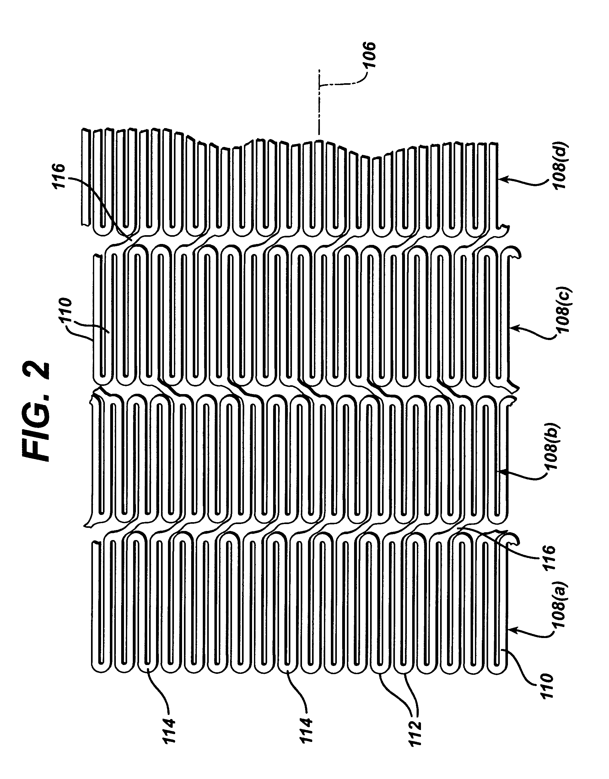
[0054]While the present invention may be used on or in connection with any number of medical devices, including stents, for ease of explanation, one exemplary embodiment of the invention with respect to self-expanding Nitinol stents will be described in detail. There is illustrated in FIGS. 1 and 2, a stent 100, which may be utilized in connection with the present invention. FIGS. 1 and 2 illustrate the exemplary stent 100 in its unexpanded or compressed state. The stent 100 is preferably made from a superelastic alloy such as Nitinol. Most preferably, the stent 100 is made from an alloy comprising from about 50.0 percent (as used herein these percentages refer to weight percentages) Ni to about 60 percent Ni, and more preferably about 55.8 percent Ni, with the remainder of the alloy being Ti. Preferably, the stent 100 is designed such that it is superelastic at body temperature, and preferably has an Af in the range from about twenty-four degrees C. to about thirty-seven degrees C....


PUM


Abstract

A stent or other intraluminal medical device may be constructed utilizing multiple, individual, independent, self-expanding stent segments which are designed to interlock when constrained within a delivery sheath and uncouple upon deployment. The individual segments are releasably connected by a series of bridging elements and receptacles.

Description

BACKGROUND OF THE INVENTION[0001]1. Field of the Invention[0002]The present invention relates to stents having a modified bridge design and more particularly to stents having an anvil bridge design. In addition the present invention relates to intraluminal devices, and more particularly to intraluminal devices, such as stents, incorporating integral markers for increasing the radiopacity thereof. The present invention also relates to stent structures constructed from independent, interlocking stent segments which uncouple once deployed.[0003]2. Discussion of Related Art[0004]Percutaneous transluminal angioplasty (PTA) is a therapeutic medical procedure used to increase blood flow through an artery. In this procedure, the angioplasty balloon is inflated within the stenosed vessel, or body passageway, in order to shear and disrupt the wall components of the vessel to obtain an enlarged lumen. With respect to arterial stenosed lesions, the relatively incompressible plaque remains unalt...

Claims


Application Information

Patent Timeline
Patent Type & Authority Patents(United States)
IPC IPC(8): A61F2/06A61F2/00A61F2/82
CPCA61F2/91A61F2/915A61F2/89A61F2/852A61F2002/91516A61F2002/91533A61F2230/0054A61F2002/91591A61F2250/0063A61F2250/0098A61F2002/826A61F2002/91558
Inventor BONSIGNORE, CRAIGJOHNSON, KIRK
Owner CARDINAL HEALTH SWITZERLAND 515 GMBH
Why Eureka
Try Eureka