[0017]The present invention overcomes the disadvantages associated with undesirable loading effects during stent loading and
stent deployment as briefly discussed above. The present invention also overcomes many of the disadvantages associated with reduced radiopacity exhibited by self-expanding stents,
balloon-expandable stents, and other medical devices as briefly discussed above.
[0019]
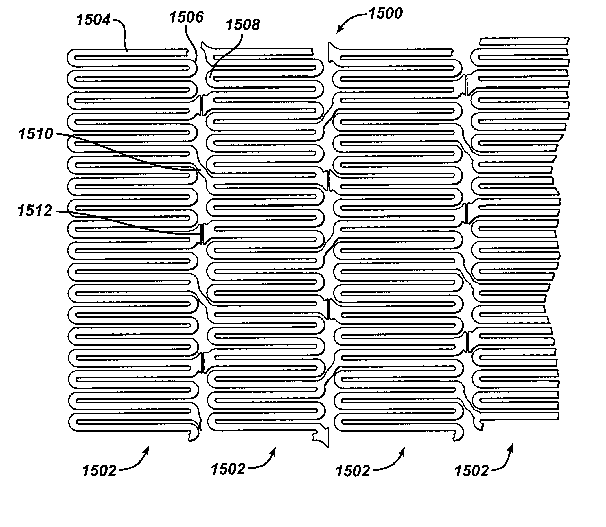
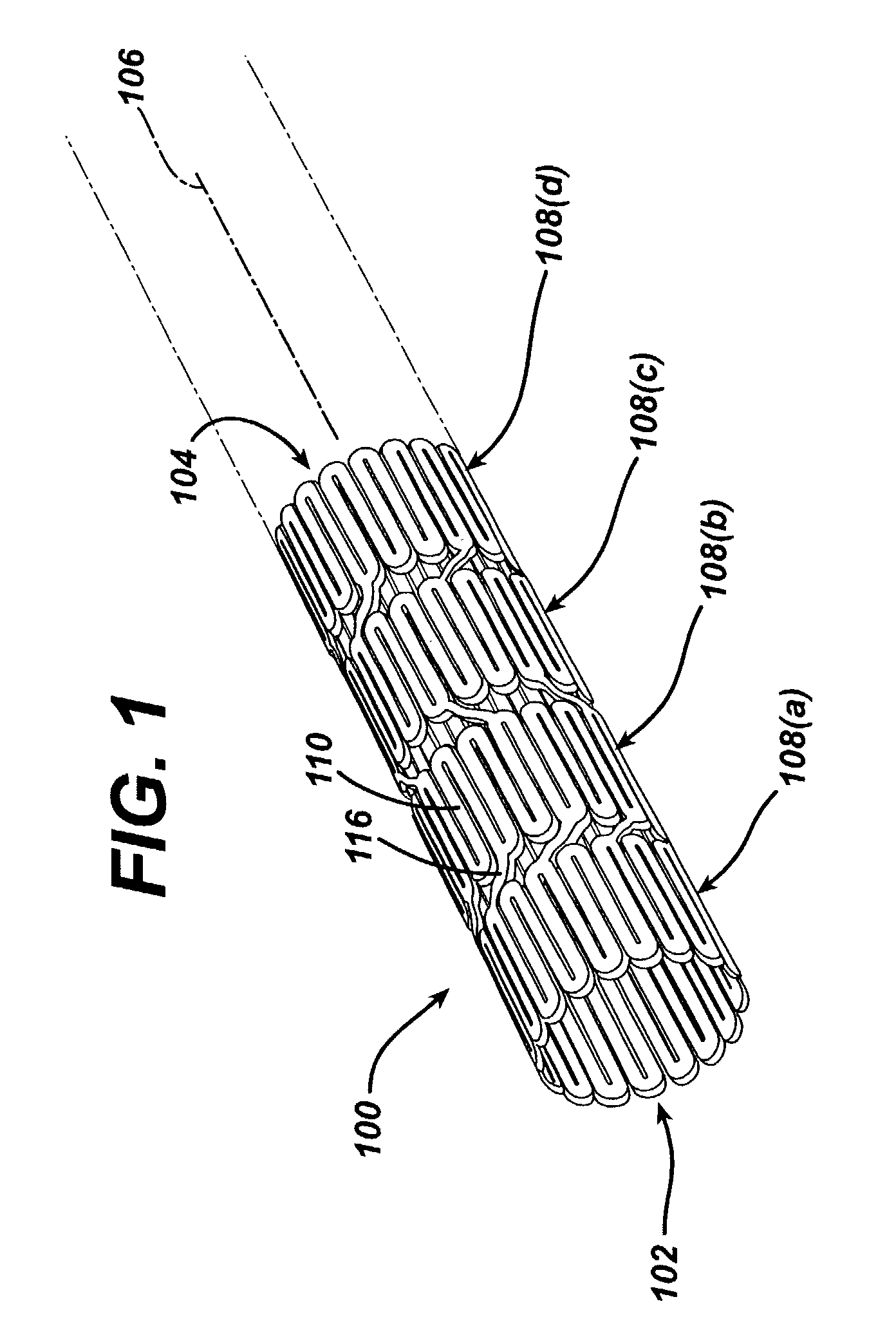
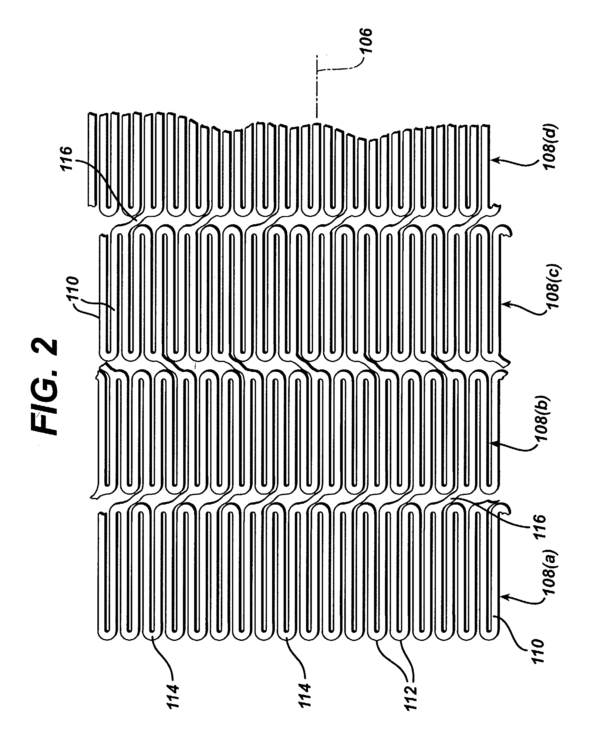
Stent structures are often constructed of radially expanding members or hoops connected by bridge elements. In certain stent designs, the bridge elements may connect every tip or loop of the radially expanding members or hoops to a corresponding tip or loop of an adjacent radially expanding member or hoop. This type of design provides for a less flexible stent. In other stent designs, the bridge elements do not connect every set of tips or loops, but rather, the bridges are placed periodically. When bridges are periodically spaced, open gaps may exist between unconnected tips or loops. This design affords increased flexibility, however, potential deformation of the unconnected tips or loops may occur when the stent is subject to compressive axial loading, for example, during loading of the stent into the stent
delivery system or during deployment of the stent. The split-bridge design of the present invention may be utilized to effectively fill the gap between adjacent unconnected tips or loops without serving as a structural connection point between such tips or loops. Accordingly, there is no sacrifice in terms of flexibility.
[0020]In addition, the split-bridge design serves to increase the surface area of the stent. This increased surface area may be utilized to modify a
drug release profile by increasing the amount of
drug available for
drug delivery. Essentially, increased surface area on the stent allows for more drugs
coating thereon.
[0021]The intraluminal
medical device of the present invention may utilize high radiopacity markers to ensure proper positioning of the device within a lumen. The markers comprise a housing that is integral to the device itself, thereby ensuring minimal interference with deployment and operation of the device. The housings are also shaped to minimally
impact the overall profile of the stent. For example, a properly shaped housing allows a stent to maintain a radiopaque stent marker size utilized in a seven French
delivery system to fit into a six French
delivery system. The markers also comprise a properly sized marker insert having a higher radiopacity than the material forming the device itself. The marker insert is sized to match the curvature of the housing thereby ensuring a tight and unobtrusive fit. The marker inserts are made from a material close in the galvanic series to the
device material and sized to substantially minimize the effect of
galvanic corrosion.
[0022]The improved radiopacity intraluminal
medical device of the present invention provides for more precise placement and post-procedural
visualization in a lumen by increasing the radiopacity of the device under X-
ray fluoroscopy. Given that the marker housings are integral to the device, they are simpler and less expensive to manufacture than markers that have to be attached in a separate process.
[0023]The improved radiopacity intraluminal medical device of the present invention is manufactured utilizing a process, which ensures that the marker insert is securely positioned within the marker housing. The marker housing is
laser cut from the same tube and is integral to the device. As a result of the
laser cutting process, the hole in the marker housing is conical in the radial direction with the outer surface
diameter being larger than the inner surface
diameter. The conical tapering effect in the marker housing is beneficial in providing an
interference fit between the marker insert and the marker housing to prevent the marker insert from being dislodged once the device is deployed. The marker inserts are loaded into a crimped device by
punching a disk from annealed ribbon stock-and shaping it to have the same
radius of curvature as the marker housing. Once the disk is loaded into the marker housing, a coining process is used to properly seat the marker below the surface of the housing. The coining punch is also shaped to maintain the same
radius of curvature as the marker housing. The coining process deforms the marker housing material to form a protrusion, thereby locking in the insert or disk.

