Polymeric marker with high radiopacity

a polymer marker and radiopacity technology, applied in the direction of radiation diagnostic clinical applications, conductive materials, chemical vapor deposition coating, etc., can solve the problems of metallic markers that are relatively expensive to manufacture, undesirable discontinuities, and catheter shafts, and achieves a large profile, reduce the flow of polymeric materials, and reduce the effect of stent deploymen

Active Publication Date: 2005-03-24
ABBOTT CARDIOVASCULAR
View PDF42 Cites 36 Cited by
  • Summary
  • Abstract
  • Description
  • Claims
  • Application Information

AI Technical Summary

Benefits of technology

[0013] During melt bonding, the polymeric marker is heated to an elevated temperature sufficient to melt the polymeric material to produce the melt bond. However, in one presently preferred embodiment, the elevated temperature is low enough to minimize or prevent flowing of the polymeric material of the marker. Consequently, the double wall thickness (inner diameter minus outer diameter) of the polymeric marker after melt bonding is equal to or not substantially less than (i.e., not more than about 5 to about 25% less than) the double wall thickness prior to melt bonding. Although some rounding of the edges of the polymeric marker may occur during melt bonding, the maximum wall thickness of the polymeric marker is preferably not reduced during the melt bonding. The marker radiopacity is strongly affected by both the percent loading of radiopaque material and the final wall thickness of the marker. Consequently, the percent loading of radiopaque material and the wall thickness of the finished marker are carefully controlled to provide the desired radiopacity. If the wall thickness of the polymeric marker is less than the required minimum wall thickness, the radiopacity of the marker will be too low. On the other hand, if the outer diameter / wall thickness of the polymeric marker is greater than the required maximum outer diameter / wall thickness, the large profile and added stiffness of the marker will disadvantageously affect catheter performance. Thus, the hot die necked extrusion has an outer diameter and wall thickness which is within the minimum and maximum desired values, so that little or no thinning of the marker is required during melt bonding of the marker to provide the desired outer diameter. As a result, a decrease in wall thickness which can reduce the radiopacity of the finished marker is prevented or minimized during bonding. In one embodiment, the polymeric marker is adhesively bonded to the medical device or component, and as a result, the wall thickness of the marker is not affected by the bonding process.
[0014] Due to its high radiopacity, flexibility and melt bondability, the marker of the present invention is readily attached to for example the inner member of a balloon catheter, a guidewire, and even a guide catheter tip. The attachment of radiopaque markers of known dimensions to a guidewire or the attachment to a guidewire of multiple radiopaque markers with known separation distances impart a measurement capability to the catheter that allows a physician to quickly and easily measure lesions and decide on appropriate stent lengths.

Problems solved by technology

Such configuration, however, locally stiffens the catheter shaft and thereby imparts an undesirable discontinuity thereto as the solid metal bands are relatively inflexible compared to a polymer balloon catheter shaft.
Additionally, the metallic markers are relatively expensive to manufacture and relatively difficult to positively affix to an underlying device.

Method used


Image

  • Polymeric marker with high radiopacity
  • Polymeric marker with high radiopacity

Examples


Embodiment Construction

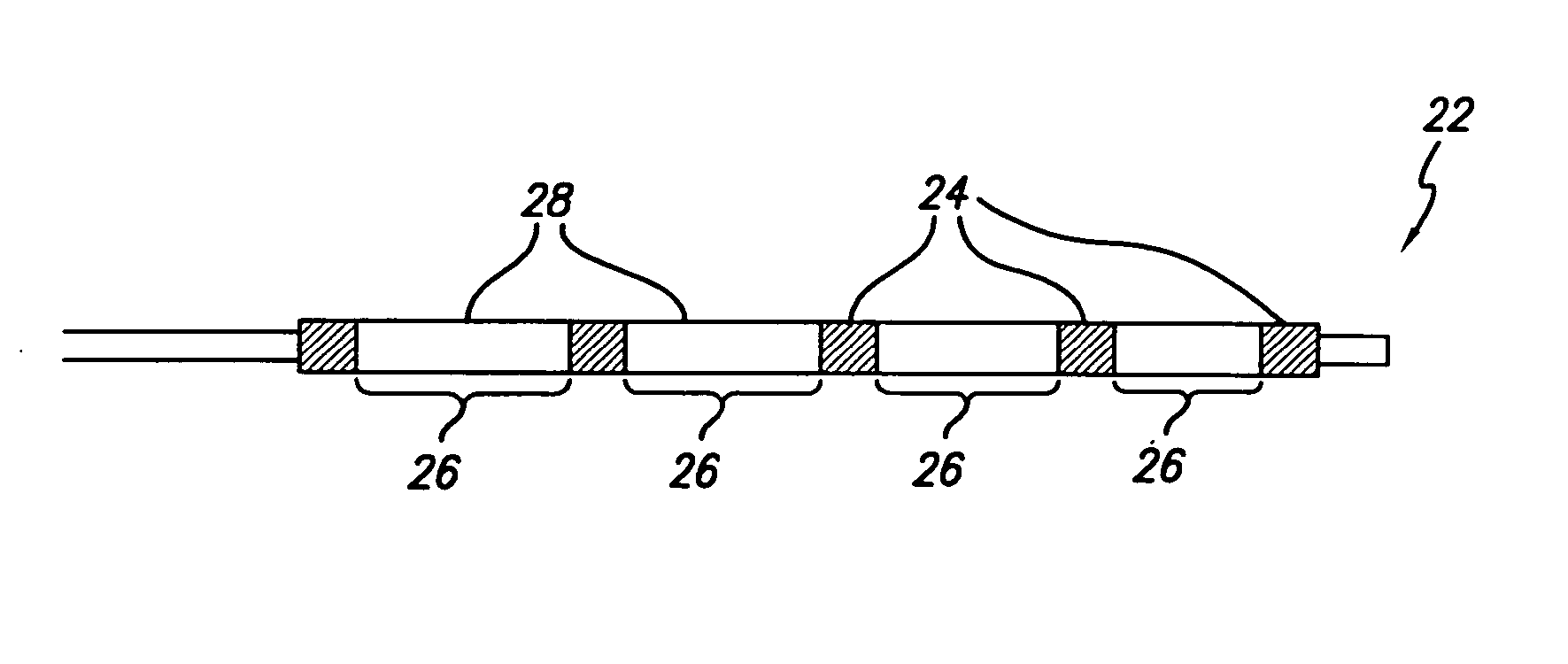
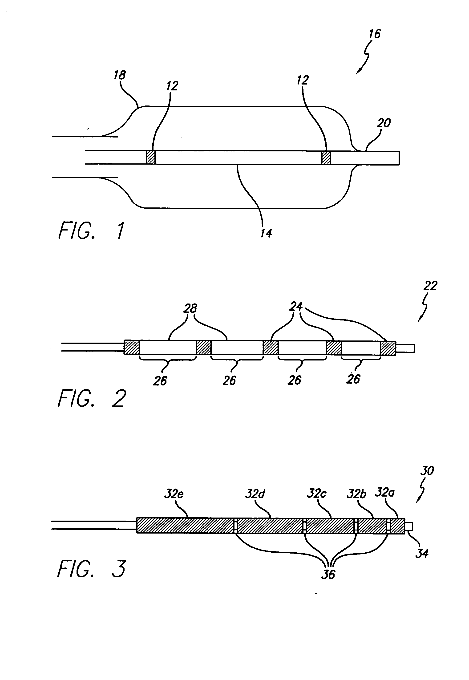
[0019] The present invention provides a radiopaque marker for use on a variety of devices that is flexible, highly radiopaque and is easily attachable to such devices by melt bonding. These properties allow markers to be of minimal thickness and thereby minimize the effect the marker has on the overall profile and stiffness of the device to which it is to be attached.

[0020] In order to achieve the high fill ratios that are necessary to attain the desired radiopacity and in order to do so without compromising the compoundability and workability of the polymeric material nor its ultimate strength and flexibility, a number of different parameters have been found to be of importance. More specifically, both the particle shape and particle size of the radiopaque agent must be carefully controlled while the inclusion of a wetting agent such as MA-g-PO in the polymer blend is critical. An antioxidant may additionally be included in an effort to reduce the adverse effect the high processin...


PUM

PropertyMeasurementUnit
diameteraaaaaaaaaa
diameteraaaaaaaaaa
volume percentaaaaaaaaaa

Abstract

High radiopacity is achieved in a polymeric marker by combining a polymeric resin, a powdered radiopaque agent having uniformly shaped particles of a specific particle size distribution and a wetting agent. The method to produce the marker calls for the blending and pelletization of these materials followed by extrusion onto support beading. The resulting supported tubing is subsequently cut to length with the beading still in place. After ejection of the beading remnant the marker is slipped into place on the device to be marked and attached by melt bonding. Marking of a guidewire allows lesions to be measured while the marking of balloon catheters allow the balloon to be properly positioned relative to a lesion.

Description

BACKGROUND OF THE INVENTION [0001] The present invention is directed to elongated intracorporeal devices, and more particularly intraluminal devices for stent deployment, percutaneous transluminal coronary angioplasty (PTCA), and the similar procedures. PTCA is a widely used procedure for the treatment of coronary heart disease. In this procedure, a balloon dilatation catheter is advanced into the patient's coronary artery and the balloon on the catheter is inflated within the stenotic region of the patient's artery to open up the arterial passageway and increase the blood flow through the artery. To facilitate the advancement of the dilatation catheter into the patient's coronary artery, a guiding catheter having a preshaped distal tip is first percutaneously introduced into the cardiovascular system of a patient by the Seldinger technique through the brachial or femoral arteries. The catheter is advanced therein until the preshaped distal tip of the guiding catheter is disposed wi...

Claims


Application Information

Patent Timeline
Patent Type & Authority Applications(United States)
IPC IPC(8): A61B5/107A61B19/00A61F2/06A61F2/84A61L29/18A61L31/18A61M25/01
CPCA61B5/1076Y10T428/139A61F2/958A61F2250/0098A61L29/18A61L31/18A61M25/0108A61B6/485A61B6/12A61B5/6853A61B5/6851A61M25/09A61M25/0012A61L31/125A61M25/1027Y10T428/12493Y10T156/1089Y10T428/1372A61B19/54A61B90/39A61B2562/17
Inventor BAVARO, VINCENT PETERSIMPSON, JOHN ARTHURD'AQUANNI, PETERBALDWIN, AARON
Owner ABBOTT CARDIOVASCULAR
Why Eureka
Try Eureka