Taper locking features between components of a welding device

a technology of locking feature and welding device, which is applied in the direction of soldering device, manufacturing tool,auxillary welding device, etc., can solve the problem that one connection may have a tendency to come apart before the other, and achieve the effect of improving heat transfer and electrical conductivity, prolonging the useful life of components, and reducing the chance of overheating

a technology of locking feature and welding device, which is applied in the direction of soldering device, manufacturing tool,auxillary welding device, etc., can solve the problem that one connection may have a tendency to come apart before the other, and achieve the effect of improving heat transfer and electrical conductivity, prolonging the useful life of components, and reducing the chance of overheating

US7176412B2Active Publication Date: 2007-02-13ILLINOIS TOOL WORKS INC

Image

  • Taper locking features between components of a welding device
  • Taper locking features between components of a welding device
  • Taper locking features between components of a welding device

Examples


Embodiment Construction

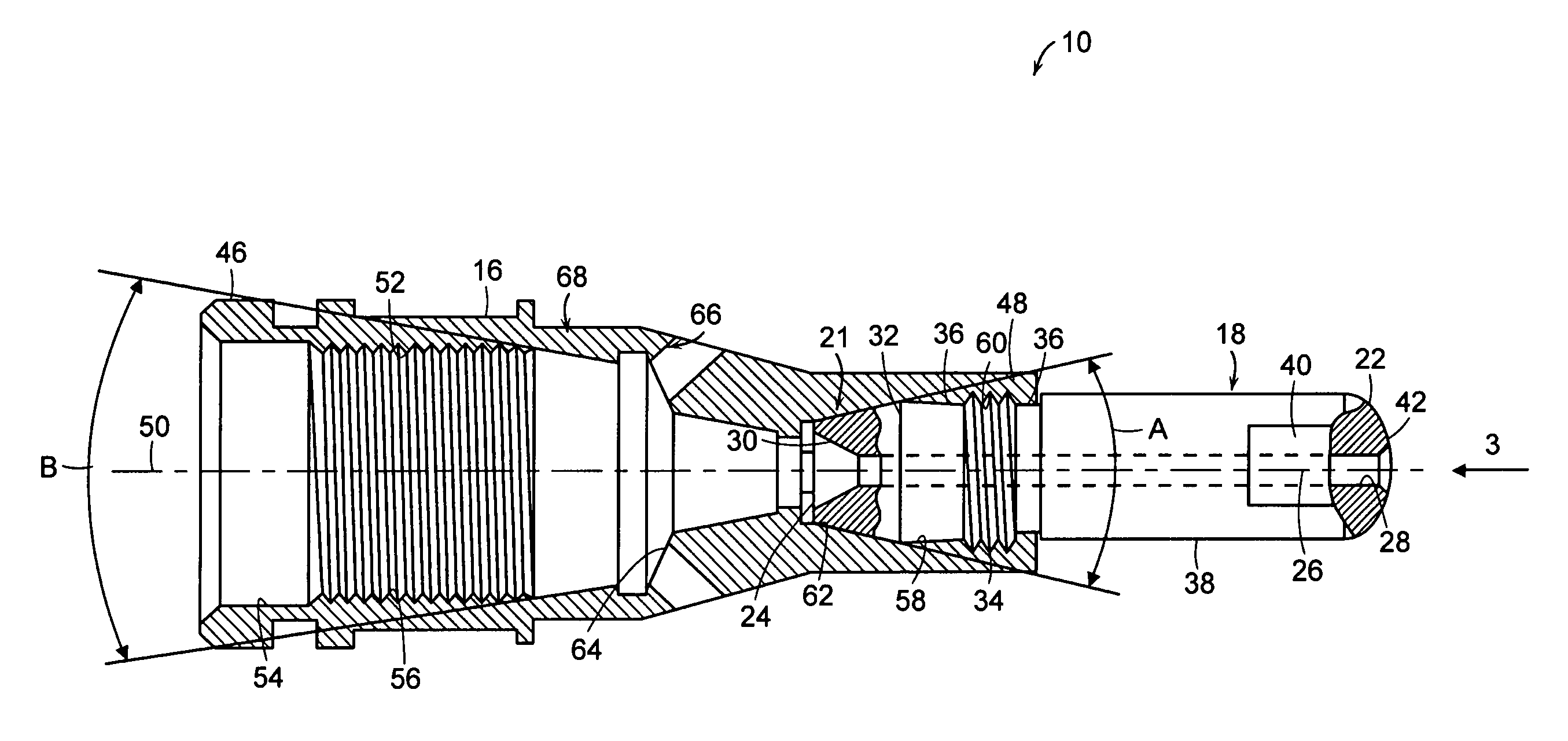
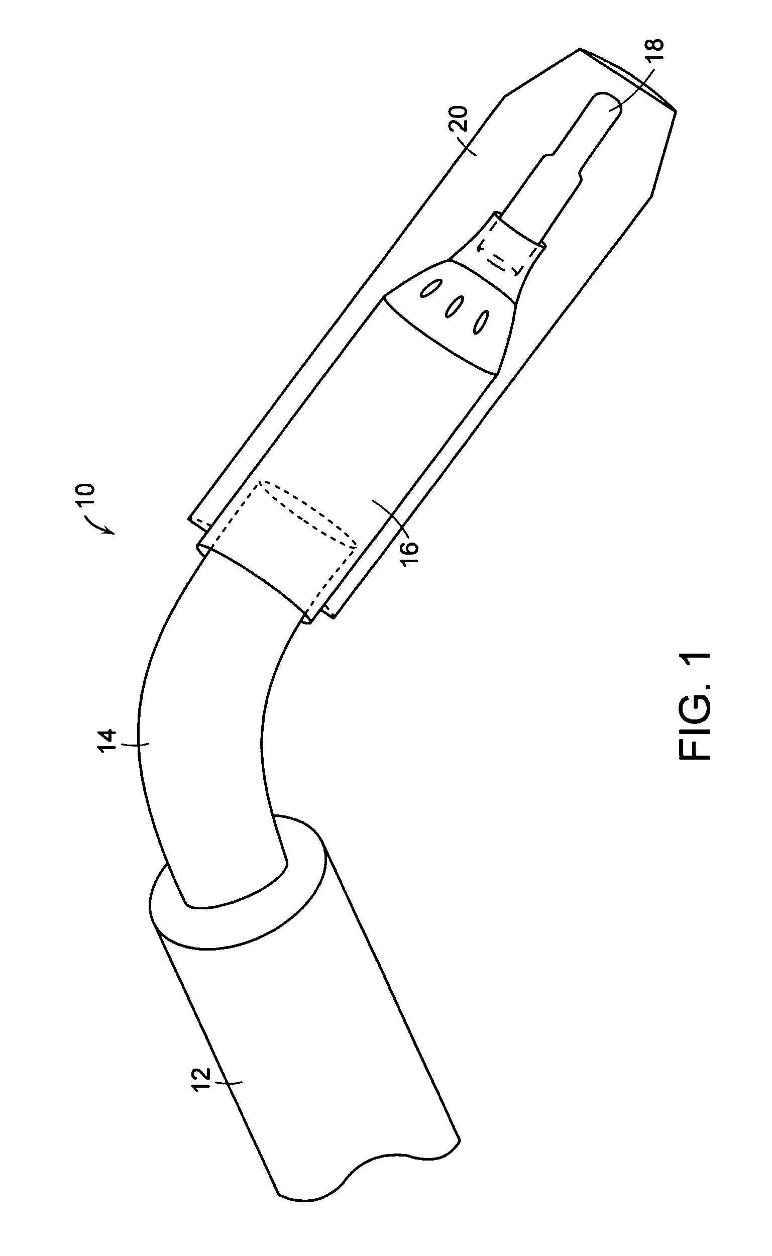
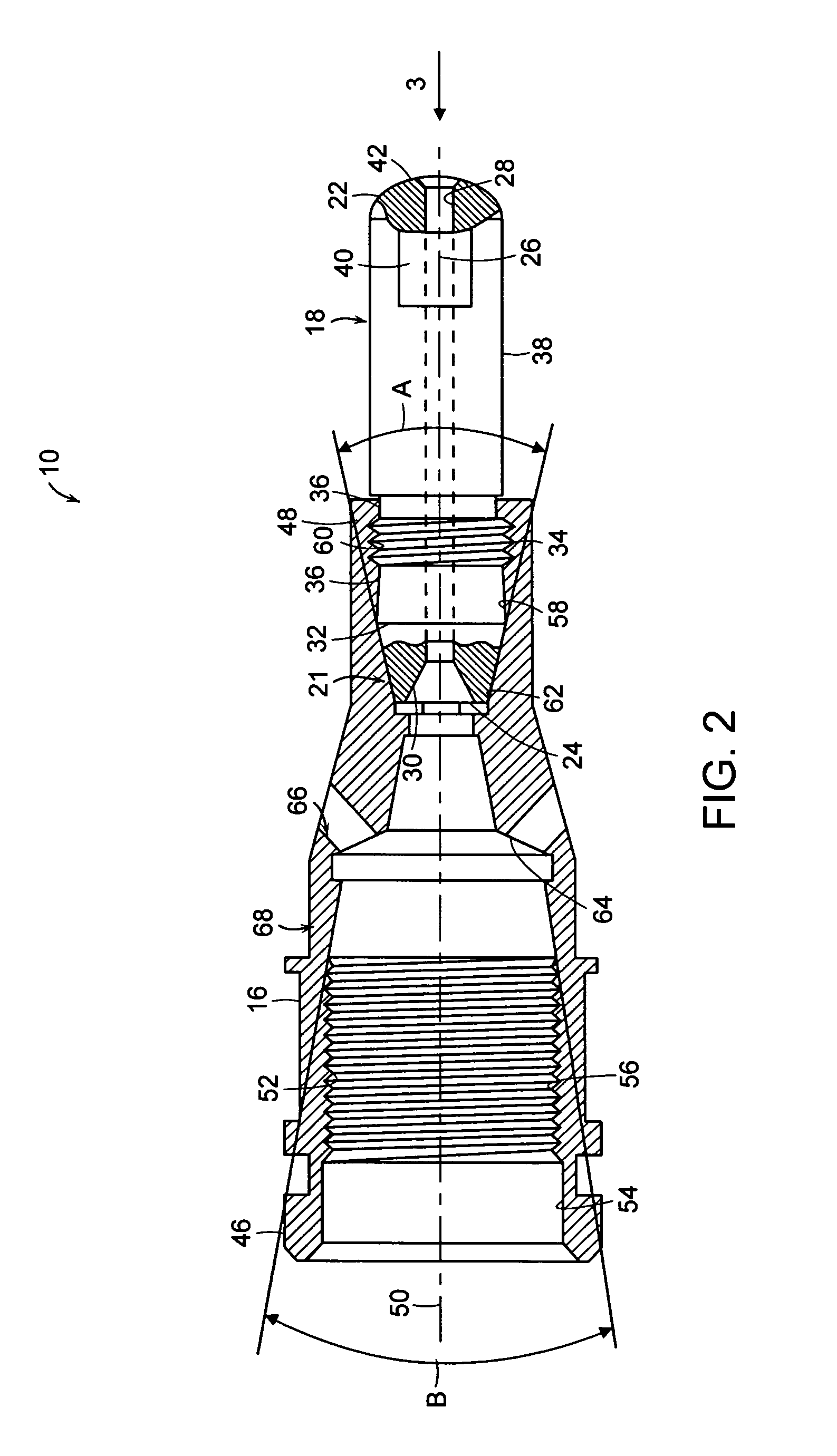
[0023]A welding device, in various embodiments of the invention, can include a plurality of components. For example, a welding gun 10, e.g., as illustrated in FIG. 1, can include a handle 12, a goose neck 14, a retaining head 16, and a contact tip 18. The welding gun 10 can also include a nozzle 20, which is shown in FIG. 1 in cross-section for clarity. The welding gun 10 can be hand-held or suitable for use by a robotic system.

[0024]In various embodiments, components of the welding device incorporate one or more locking engagement connections to ensure that the components remain engaged during service. The connections can improve and extend the useful life of the components by providing a more secure method of attachment of the components to each other or to the welding device, which reduces the chance of overheating and improves heat transfer and electrical conductivity between components.

[0025]In an embodiment using two or more locking engagement connections, one may engage with ...


PUM

PropertyMeasurementUnit
included angleaaaaaaaaaa

Abstract

Locking engagement connections between various components of a welding device can include tapered features having varied thread patterns and / or varied angles to ensure that the components remain tight during service. For example, locking engagement connections can be incorporated between a nozzle and a retaining head, a retaining head and a gooseneck, and / or a contact tip and a retaining head.

Description

CROSS-REFERENCE TO RELATED APPLICATION[0001]This application claims the benefits of and priority to U.S. Provisional Patent Application Ser. No. 60 / 558,236 filed on Mar. 31, 2004, which is owned by the assignee of the instant application and the disclosure of which is incorporated herein by reference in its entirety.FIELD OF THE INVENTION[0002]The invention relates generally to welding devices, and more particularly to locking engagement connections between components of a welding gun.BACKGROUND OF THE INVENTION[0003]Welding equipment, e.g., metal inert gas (MIG) welding equipment, can be used for welding one metal workpiece to another metal workpiece. A welding gun can be designed to allow a user or robot to direct a metal welding wire toward a specific location on a target metal workpiece. The components of a typical welding gun include a handle, a gooseneck, a retaining head, a contact tip, and a nozzle. The welding wire is fed through the welding gun, and ultimately through a pa...

Claims


Application Information

Patent Timeline
13 Feb 2007
Publication
US7176412B2
IPC
B23K9/28; B23K9/24; B23K9/29; B23K9/32; B23K37/00; B23K37/04; B23K37/053
CPC
B23K9/32; B23K9/291
Inventors
WELLS, JEFF G.