Piezoelectric element and touch screen utilizing the same

a technology of piezoelectric elements and touch screens, applied in static indicating devices, instruments, device material selection, etc., can solve the problem of insufficiently high electro-mechanical conversion rate that cannot be obtained, and achieve the effect of higher electro-mechanical conversion ra

Inactive Publication Date: 2007-02-13
FUJITSU LTD
View PDF24 Cites 88 Cited by
  • Summary
  • Abstract
  • Description
  • Claims
  • Application Information

AI Technical Summary

Benefits of technology

[0016]Preferably, the piezoelectric layer may be formed of ZnO doped with Mn. This arrangement is advantageous for preventing e.g. Al contained in the first electrode from diffusing into the piezoelectric layer. As a result, the piezoelectric element can maintain the high electro-mechanical conversion rate.

Problems solved by technology

In the prior art devices, however, a sufficiently high electro-mechanical conversion rate fails to be obtained as the thickness h of the piezoelectric layer is made smaller, even if the above relation 0.005≦h / λ≦0.1 is observed.

Method used


Image

  • Piezoelectric element and touch screen utilizing the same
  • Piezoelectric element and touch screen utilizing the same
  • Piezoelectric element and touch screen utilizing the same

Examples


first embodiment

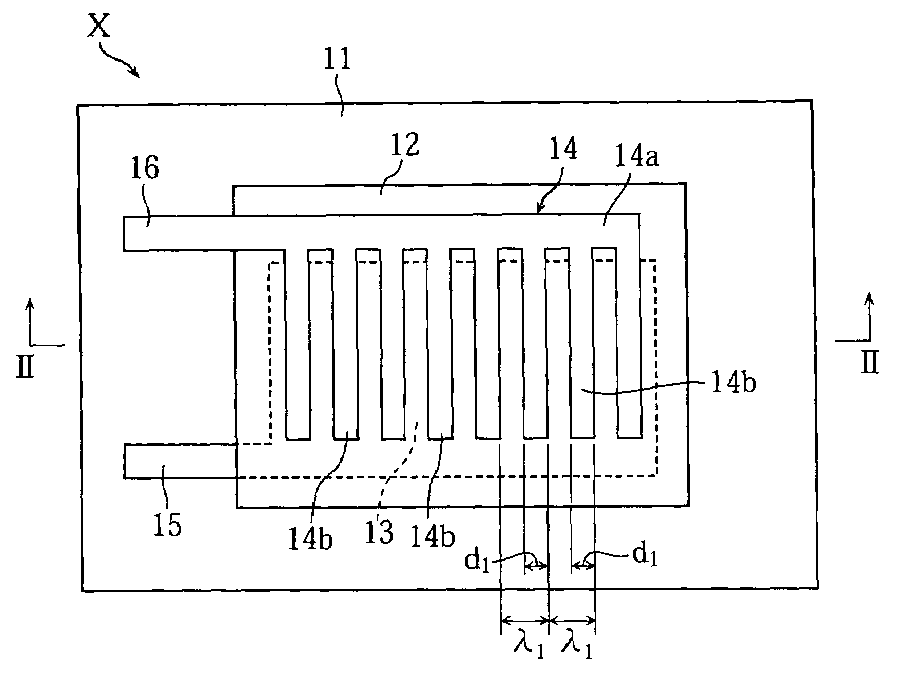
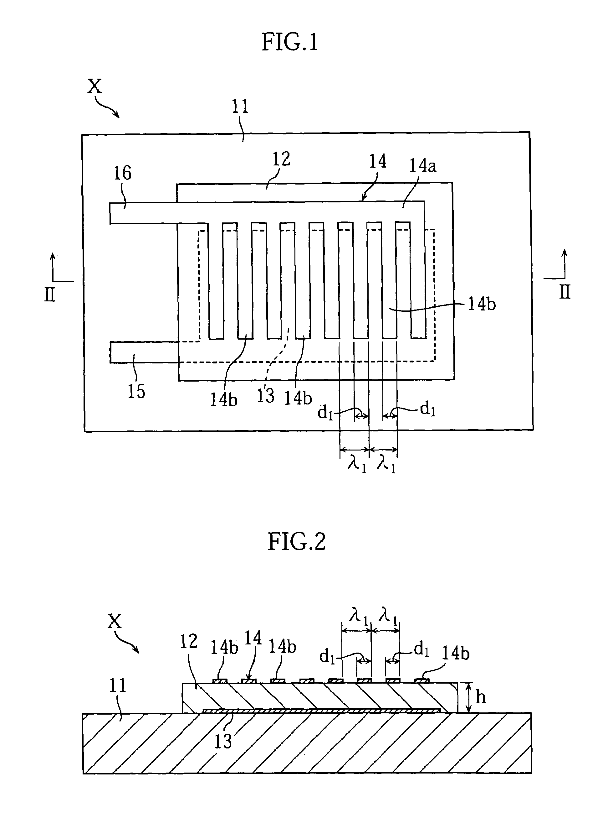
[0034]Reference is first made to FIGS. 1 and 2 illustrating a piezoelectric element X according to the present invention. FIG. 1 is a plan view showing the piezoelectric element X, while FIG. 2 is a sectional view taken along lines II—II in FIG. 1. The piezoelectric element X, including a substrate 11, a piezoelectric layer 12 and electrodes 13 and 14, is arranged to generate and receive surface acoustic waves.

[0035]The substrate 11 is rigid enough to ensure the integrity of the piezoelectric element and serves as a medium to propagate surface acoustic waves. The substrate 11 is formed of a non-piezoelectric material such as glass.

[0036]The piezoelectric layer 12 is made of a piezoelectric material, thereby exhibiting the piezoelectric effect (the generation of electric polarization as a result of the application of mechanical stress) and the reverse piezoelectric effect (the production of a mechanical distortion as a result of the application of a voltage). Examples of piezoelectri...

second embodiment

[0055]In the second embodiment again, the hillock occurrence rate for the electrode 23 is no greater than 0.1%. The electrode 23 is formed of a metal material such as aluminum alloy. Preferably, the Al alloy contains 0.1˜3.0 wt % of a metal selected from the group consisting of Ti, Cr, Ni, Cu, Zn, Pd, Ag, Hf, W, Pt and Au. Advantageously, the electrode 23 made of such an Al alloy has a smaller thermal expansion coefficient than a counterpart electrode made of pure aluminum. Accordingly, the occurrence and growth of hillocks on the electrode 23 can be appropriately restricted to ensure 0.1% or smaller hillock occurrence rate.

[0056]The upper electrode 24 is formed on the piezoelectric layer 12. The electrode 24 may be made of the same conductive material as that used for making the lower electrode 23. The thickness of the electrode 24 is 300˜600 nm, for example. The electrode 24 faces the respective branches 23b of the lower electrode via the piezoelectric layer 12, and is connected t...

third embodiment

[0063]Reference is now made to FIGS. 8 and 9 illustrating a SAW touch screen Y according to the present invention. The touch screen Y includes a substrate 31, a piezoelectric layer 32, lower electrodes 33A˜33D and upper electrodes 34A˜34D. For clarity of illustration, the piezoelectric layer 32 is depicted in double-dot chain lines.

[0064]The substrate 31 is a transparent plate through which surface acoustic waves propagate. The substrate 31 includes a detection region 31a and a marginal region 31b. In the figures, the boundary between the detection region 31a and the marginal region 31b is indicated by broken lines. The substrate 31 is made of a non-piezoelectric material such as glass and has a thickness of 0.7˜1.1 mm. In the illustrated example, the detection region 31a is rectangular (precisely, square), though the present invention is not limited to this. The detection region 31a is surrounded by the marginal region 31b, in which wave generators and wave receivers (to be describ...


PUM

PropertyMeasurementUnit
heightaaaaaaaaaa
thicknessaaaaaaaaaa
width d1aaaaaaaaaa

Abstract

A piezoelectric element includes a substrate, a lower electrode on the substrate, a piezoelectric layer on the lower electrode, and an upper electrode on the piezoelectric layer. The upper electrode includes a common base and a plurality of parallel branches extending from the base. The branches are arranged at a regular interval or pitch λ1. The lower electrode faces the branches of the upper electrode via the piezoelectric layer. The thickness h of the piezoelectric layer and the branch pitch λ1 are determined to satisfy an inequality 0.005≦h / λ1≦0.1. The lower electrode has a hillock occurrence rate which is no greater than 0.1%.

Description

BACKGROUND OF THE INVENTION[0001]1. Field of the Invention[0002]The present invention relates to a piezoelectric element to generate or receive surface acoustic waves. The present invention also relates to a SAW touch screen incorporating piezoelectric elements used as a wave generator or receiver.[0003]2. Description of the Related Art[0004]Touch screens or touch panels are used as data input units to enable users to interact with a computer system for e.g. factory automation equipment, office automation equipment or automatic measuring device. As known, a touch screen is a force-sensitive device designed to detect an area on the screen that the user touches with his or her finger, for example. The computer system performs required data processing based on the information of a location detected by the touch screen and other necessary data.[0005]Recently, attention has been drawn to “SAW” touch screens in which the touched area is detected based on the surface acoustic wave (SAW). A...

Claims


Application Information

Patent Timeline
Patent Type & Authority Patents(United States)
IPC IPC(8): G09G5/00G06F3/043G06F3/03G06F3/041H01L41/047H01L41/09H01L41/18H01L41/22H01L41/29H03H3/08H03H9/145
CPCG06F3/0436H03H3/08H01L41/047H10N30/877H10N30/87B29D35/0054B29D35/142B29D35/148
Inventor KATSUKI, TAKASHINAKAZAWA, FUMIHIKOSANO, SATOSHITAKAHASHI, YUJI
Owner FUJITSU LTD
Why Eureka
Try Eureka