Biasing for tri-layer magnetoresistive sensors

a tri-layer magnetoresistive sensor and biasing technology, applied in the field of magnetic data storage and retrieval systems, can solve the problem that the sensor has the potential to exhibit an undesirable magnetic response to applied magnetic disc fields

Inactive Publication Date: 2007-02-13
SEAGATE TECH LLC
View PDF21 Cites 73 Cited by
  • Summary
  • Abstract
  • Description
  • Claims
  • Application Information

AI Technical Summary

Problems solved by technology

As MR sensors become smaller in size, particularly for sensors with dimensions less than about 0.1 micrometers (μm), the sensors have the potential to exhibit an undesirable magnetic response to applied fields from the magnetic disc.

Method used


Image

  • Biasing for tri-layer magnetoresistive sensors
  • Biasing for tri-layer magnetoresistive sensors
  • Biasing for tri-layer magnetoresistive sensors

Examples


Embodiment Construction

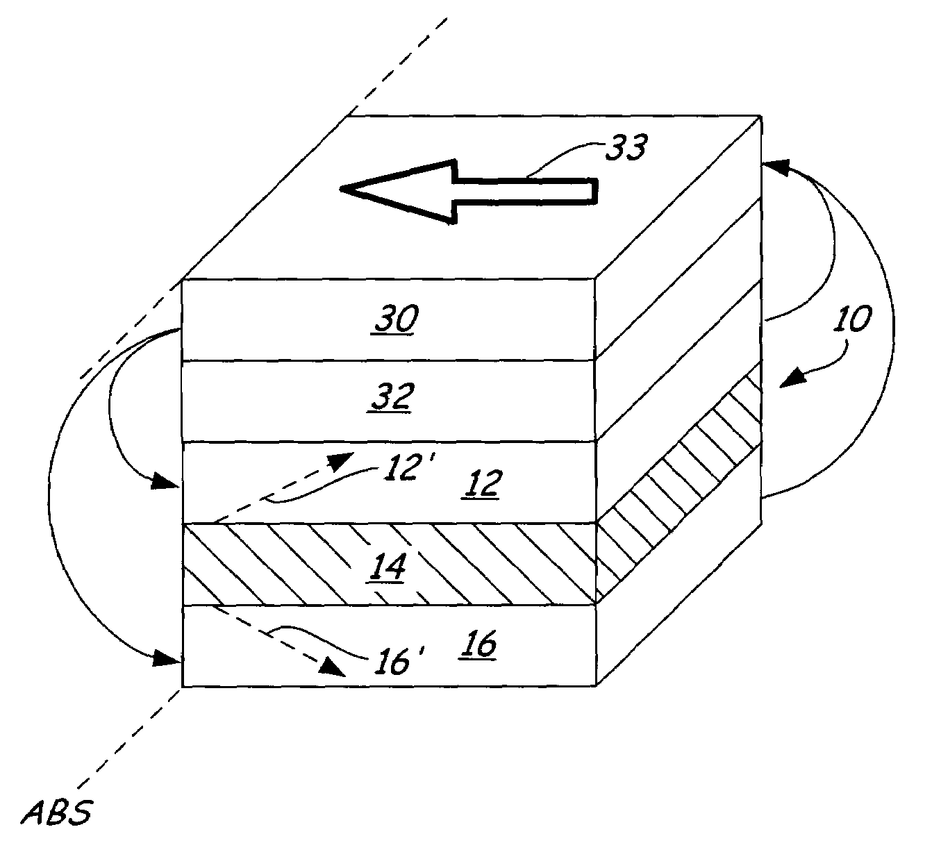
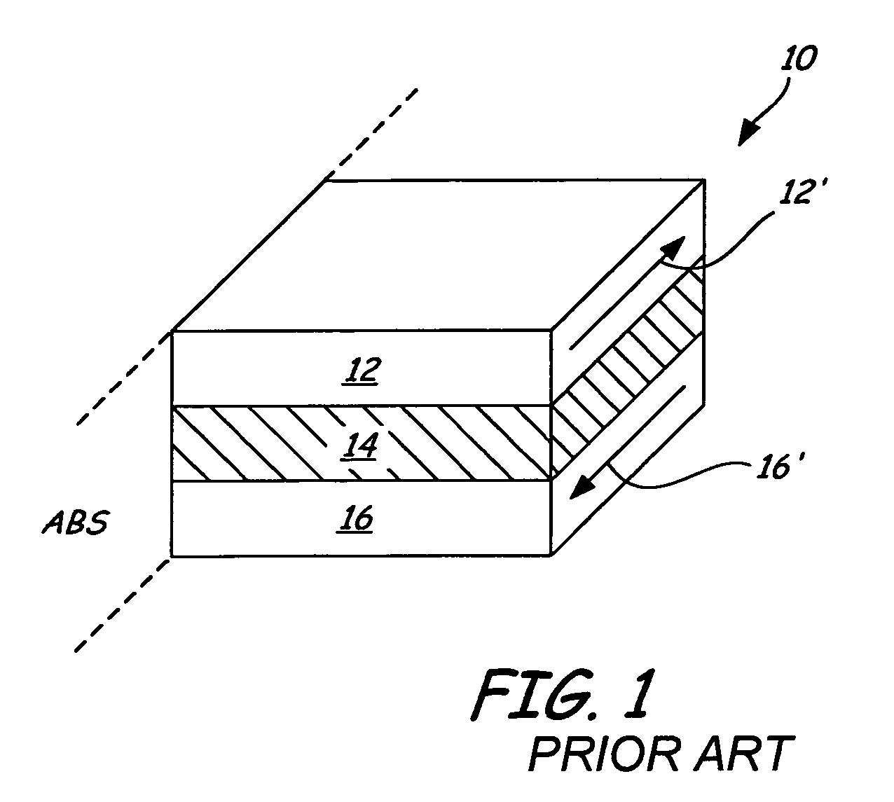
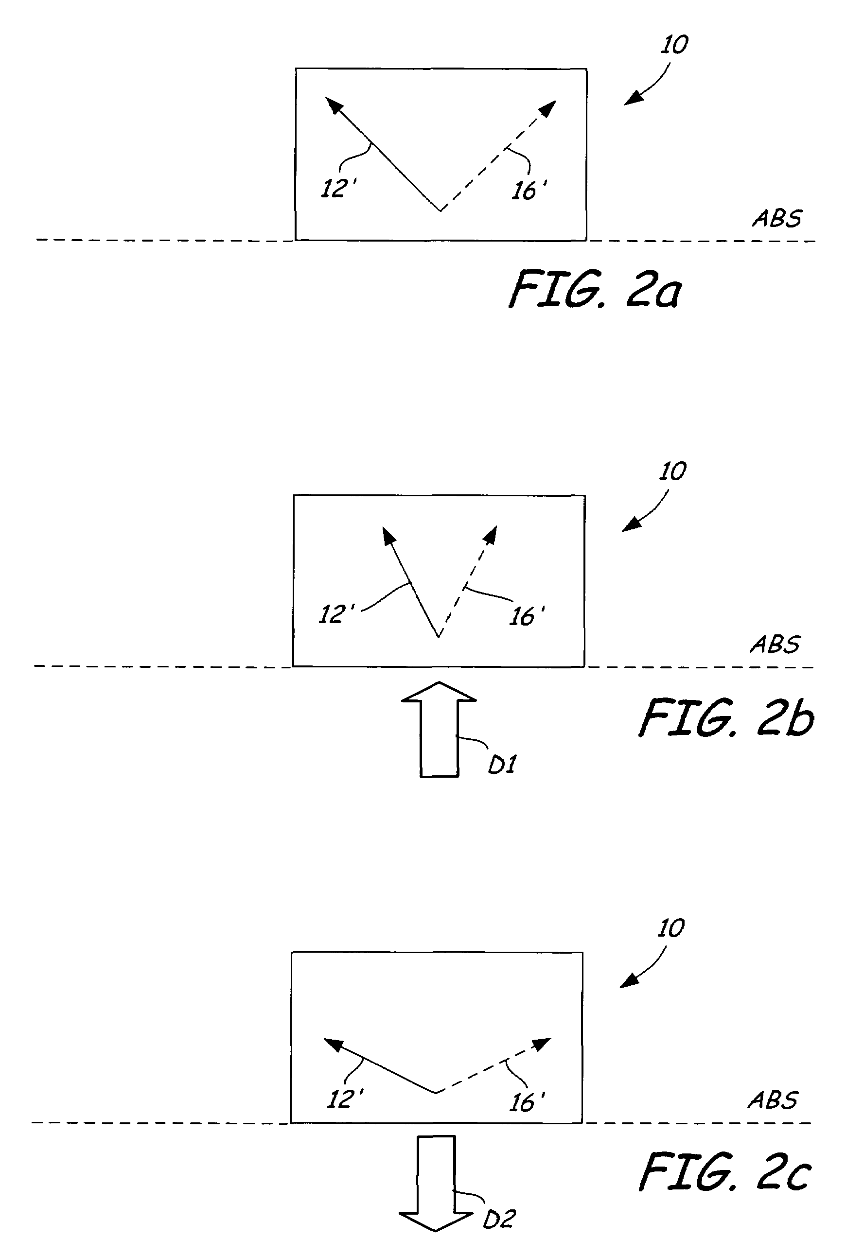
[0021]FIG. 1 shows a perspective view of tri-layer reader stack 10 in a quiescent / unbiased state. Tri-layer reader stack 10 includes first free layer 12, magnetoresistive / spacer layer 14, and second free layer 16. Magnetoresistive / spacer layer 14 is positioned between first free layer 12 and second free layer 16. Free layers 12 and 16 are preferably made of a ferromagnetic material. Magnetoresistive / spacer layer 14 may be either a tunnel barrier (to produce a tunneling magnetoresistive, or TMR, effect) or a nonmagnetic conducting spacer (to produce a giant magnetoresistive, or GMR, effect). The quiescent state / unbiased magnetization directions of free layers 12 and 16 are denoted by the arrows 12′ and 16′, respectively, on each of the free layers.

[0022]First free layer 12 and second free layer 16 have shape anisotropy induced magnetization directions. That is, the easy axes of magnetization of first free layer 12 and second free layer 16 in a quiescent / unbiased state point in a dire...


PUM

PropertyMeasurementUnit
magnetoresistiveaaaaaaaaaa
magnetizationaaaaaaaaaa
nonmagneticaaaaaaaaaa

Abstract

A biasing system for a tri-layer reader stack magnetoresistive sensor is disclosed. The tri-layer reader stack includes a first ferromagnetic free layer, a second ferromagnetic free layer, and a magnetoresistive layer between the first and second ferromagnetic free layers. The free layers are positioned in the tri-layer reader stack such that quiescent state magnetizations of the free layers are antiparallel. A biasing layer is positioned with regard to the tri-layer reader stack, typically separated from the tri-layer reader stack by a nonmagnetic spacer layer. A biasing means is positioned such that a magnetization of the biasing layer is perpendicular to the quiescent state magnetizations of the free layers. This biasing results in the free layers having biased magnetizations directed substantially orthogonal with respect to each other.

Description

BACKGROUND OF THE INVENTION[0001]The present invention relates generally to the field of magnetic data storage and retrieval systems. More particularly, the present invention relates to systems for biasing and stabilizing the free layers of a tri-layer magnetoresistive sensor stack.[0002]In a magnetic data storage and retrieval system, a magnetic recording head typically includes a reader portion having a magnetoresistive (MR) sensor for retrieving magnetically encoded information stored on a magnetic disc. Magnetic flux from the surface of the disc causes rotation of the magnetization vector of a sensing layer or layers of the MR sensor, which in turn causes a change in electrical resistivity of the MR sensor. The sensing layers are often called “free” layers, since the magnetization vectors of the sensing layers are free to rotate in response to external magnetic flux. The change in resistivity of the MR sensor can be detected by passing a current through the MR sensor and measuri...

Claims


Application Information

Patent Timeline
Patent Type & Authority Patents(United States)
IPC IPC(8): G11B5/33G11B5/127G11B5/39
CPCG11B5/3948G11B5/3909G11B5/3932G11B2005/0018G11B2005/3996
Inventor HOU, CHUNHONGMAO, SININGLINVILLE, ERIC S.HEINONEN, OLLETANG, XUEFEIHE, QINGSINGLETON, ERIC W.XUE, SONG S.
Owner SEAGATE TECH LLC
Why Eureka
Try Eureka