Measuring device for a model and machining device equipped with the same

a technology of machining device and measuring device, which is applied in the field of measuring device, can solve the problems of prone to errors in manual input solutions, and achieve the effect of reducing the risk of confusing marked workpieces

Inactive Publication Date: 2007-02-20
SIRONA DENTAL SYSTEMS
View PDF9 Cites 68 Cited by
  • Summary
  • Abstract
  • Description
  • Claims
  • Application Information

AI Technical Summary

Benefits of technology

[0017]Advantageously, the identifier is in the form of a bar code capable of being recognized by the measuring device. This makes it possible to use existing coding systems.
[0019]Advantageously, the measuring device used for measuring purposes and for recognizing the identifier is removably mounted on the machining device. This makes it possible for recording of the model and recognition of the identifier to be carried out in different places. For example, measuring can take place in the oral cavity of a patient and recognition of the identifier in the machining equipment.
[0021]The advantage of this is that identification of the workpiece must take place just prior to machining without the workpiece having to be modified in any way. This effectively avoids any incorrect assignment of workpiece information.
[0023]The machining device can be provided with a holder for releasable accommodation of the measuring device. By this means it is possible to carry out measuring at a different location, if desired.

Problems solved by technology

The first solution requires a separate bar-code reader, usually in the form of a scanner, while the second solution involving manual input is frequently prone to errors.
Here again, there is still a source of error due to the fact that following recognition of the identifier on the blank to be machined the blank might be replaced by another if, say, it should be laid aside before it has been mounted in the workpiece holder.

Method used


Image

  • Measuring device for a model and machining device equipped with the same
  • Measuring device for a model and machining device equipped with the same
  • Measuring device for a model and machining device equipped with the same

Examples


Embodiment Construction

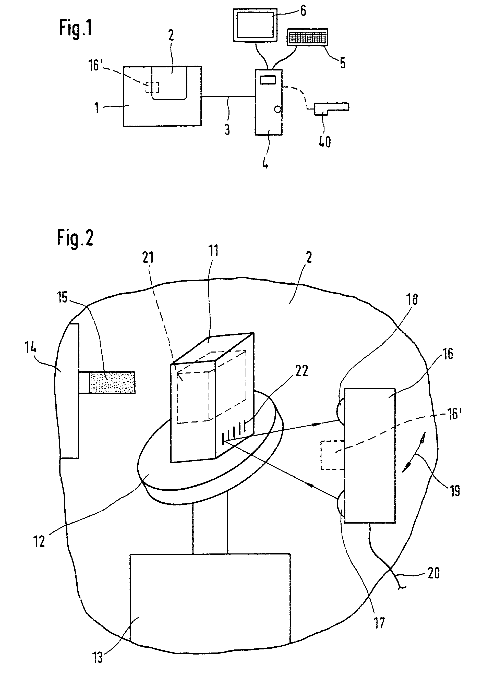
[0030]FIG. 1 illustrates a machining device 1 containing a machining chamber 2 connected by an interconnection cable 3 to a computer (PC) 4. The computer can, if desired, be incorporated in the casing of the machining equipment. PC 4 is provided with an input device in the form of a keyboard and an output device in the form of a video monitor 6. Interconnection cable 3 can transfer the data required for operation of the machining device.

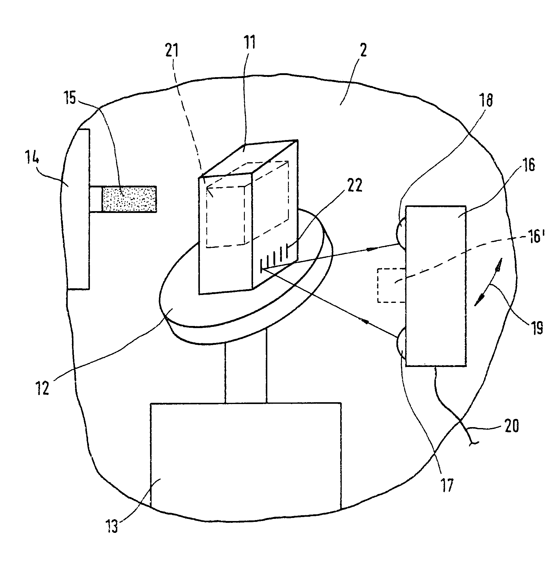
[0031]In machining chamber 2 the following operations take place: machining of a workpiece and measuring of either an original object of which a copy is to be fabricated or a three-dimensional template to be supplemented by the fitting to be fabricated, or scanning to determine the position of the workpiece to be machined.

[0032]If no measuring is to be carried out in machining chamber 2, a scanning camera 40 can be provided, which is connected to the computer and with which, for example, recordings of the interior of the mouth of the patient are made...


PUM


Abstract

The invention relates to a measuring device comprising elements for measuring models for producing dental fittings by generating a three-dimensional data record as a model for the three-dimensional machining of a workpiece. The measuring elements are configured in such a way that they can also detect an identification comprising information about the workpiece. The invention also relates to a machining device for producing dental fittings from a workpiece. The device comprises a receiving device for the workpiece, an identification comprising information about the workpiece being applied to the workpiece or workpiece holder. In addition, elements for detecting the identification of the workpiece that is held in the receiving device are provided and a single measuring device is used to measure the model and to detect the identification.

Description

FIELD OF THE INVENTION[0001]The invention relates to a measuring device, in particularly a measuring device forming part of a machining device, suitable for measuring a model for the purpose of fabricating a shaped object from, in particular, a dental ceramic. The invention also relates to machining equipment provided with such a measuring device.[0002]When blanks in the form of partially cured ceramic blocks are machined and are subjected to a sintering process following machining to achieve final strength values, they must be fabricated larger than the finished product for the reason that they shrink during the sintering process. The shrinkage parameters of, for example, dental ceramics are usually dependent on the batch from which the blanks have been formed. Thus these shrinkage parameters will have to be known prior to machining for inclusion in the computation of the semifinished product to be fabricated by such removal of material.DESCRIPTION OF RELATED ART[0003]According to ...

Claims


Application Information

Patent Timeline
Patent Type & Authority Patents(United States)
IPC IPC(8): G06K7/10A61C13/00
CPCA61C13/0022A61C13/0004
Inventor BASLER, FRANZ
Owner SIRONA DENTAL SYSTEMS
Why Eureka
Try Eureka