Retaining device for rolling-element

a technology of retaining device and rolling element, which is applied in the direction of bearings, shafts and bearings, bearings, etc., can solve the problems of increasing production costs, interfering with rolling, and affecting the rolling of rolling elements, so as to reduce friction drag

Active Publication Date: 2007-02-20
HIWIN TECH
View PDF3 Cites 20 Cited by
  • Summary
  • Abstract
  • Description
  • Claims
  • Application Information

AI Technical Summary

Benefits of technology

[0007]The primary object of the present invention is to provide a retaining device for rolling-element, which is able to reduce the friction drag, so as to make the rolling-element move smoothly.
[0008]The secondary object of the present invention is to provide a retaining device for rolling-element, in which lubricant can flow freely, so as to provide a good lubricating effect.
[0010]The retaining device for rolling-element in accordance with the present invention is of link design type. Wherein a ring structure is initially formed by ejection molding, which includes plural partitions linked by link-belt, a section of the ring structure being connectable to an opposite side portion of the ring structure, so as to make each two corresponding partitions butt-join together, the butt-joined partitions linked by the link-belt and form a space in which the rolling-element is rotatably retained. Therefore, there are flexible spaces left between the rolling-elements and the retaining device, so as to substantially reduce the friction drag of the rolling-elements with respect to the retaining device. Furthermore, the retaining device in accordance with the present invention is produced in general method of ejection molding, and thus the production cost is sharply reduced.
[0012]The present invention can also additionally designed as having a passage formed in the butt-joined partitions, so as to provide a good lubricating effect. The space of the passage is able to expand or contract so as to help the lubricant to more easily flow through the passage, and thus further improve the lubricating effect.
[0013]The retaining device for rolling-element in accordance with the present invention can be designed as having a curvature after it is turned in order to fit the shape of the circulating track of the rolling-elements, the radius of the curvature of the retaining device is no minor than that of the circulating track of the rolling element, so as to make the retaining device work smoothly.

Problems solved by technology

It is time-consuming to assemble this linear transmission unit by alternatively inserting the rolling-element and single retainer in the slide block, furthermore, the retainers and the rolling-elements are coupled with each other closely, such will cause interference in the rolling of the rolling-element.
The method of making this kind of retainer 31 is by putting the rolling-elements in a mould and made by plastic ejection molding, the material and the ejection molding machine should be high quality, thus the production cost is relatively increased.
Furthermore, due to the special manufacturing method, the retainers and the rolling elements are coupled with each other closely, such will interfere in the rolling of the rolling-element.

Method used


Image

  • Retaining device for rolling-element
  • Retaining device for rolling-element
  • Retaining device for rolling-element

Examples


Embodiment Construction

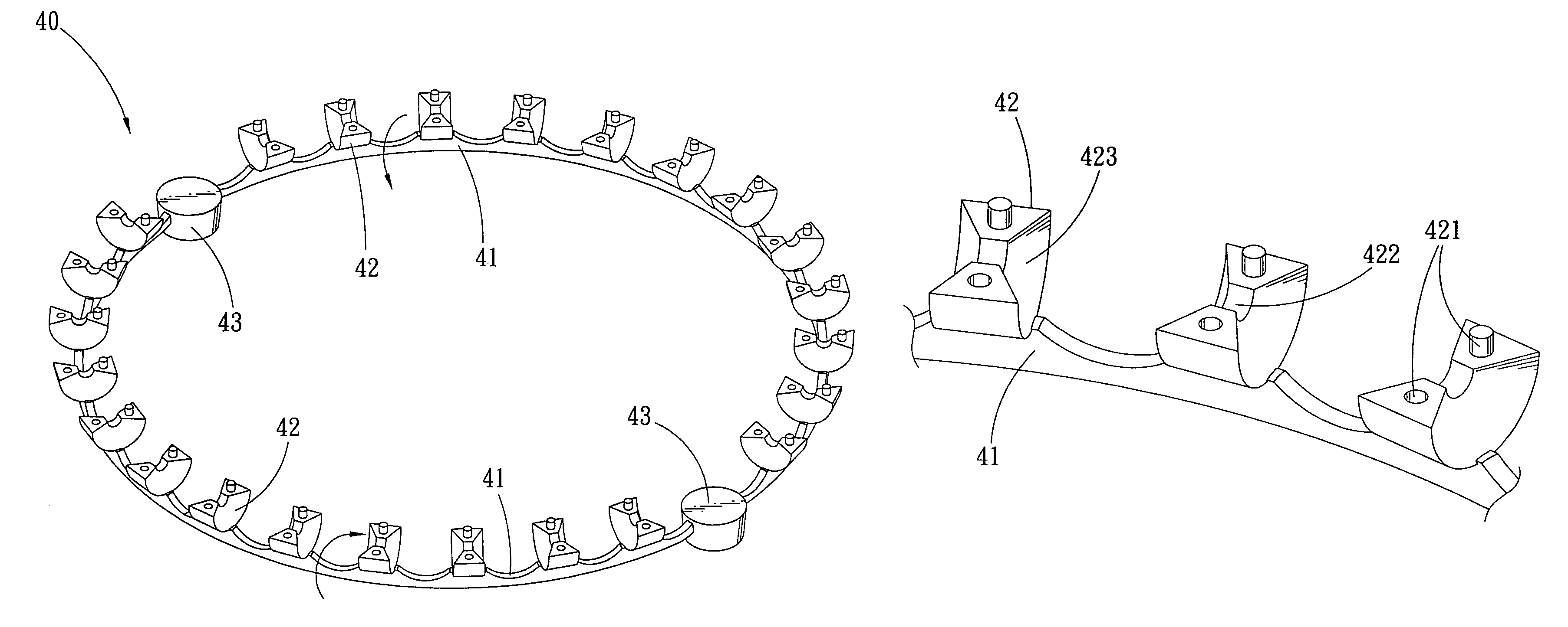
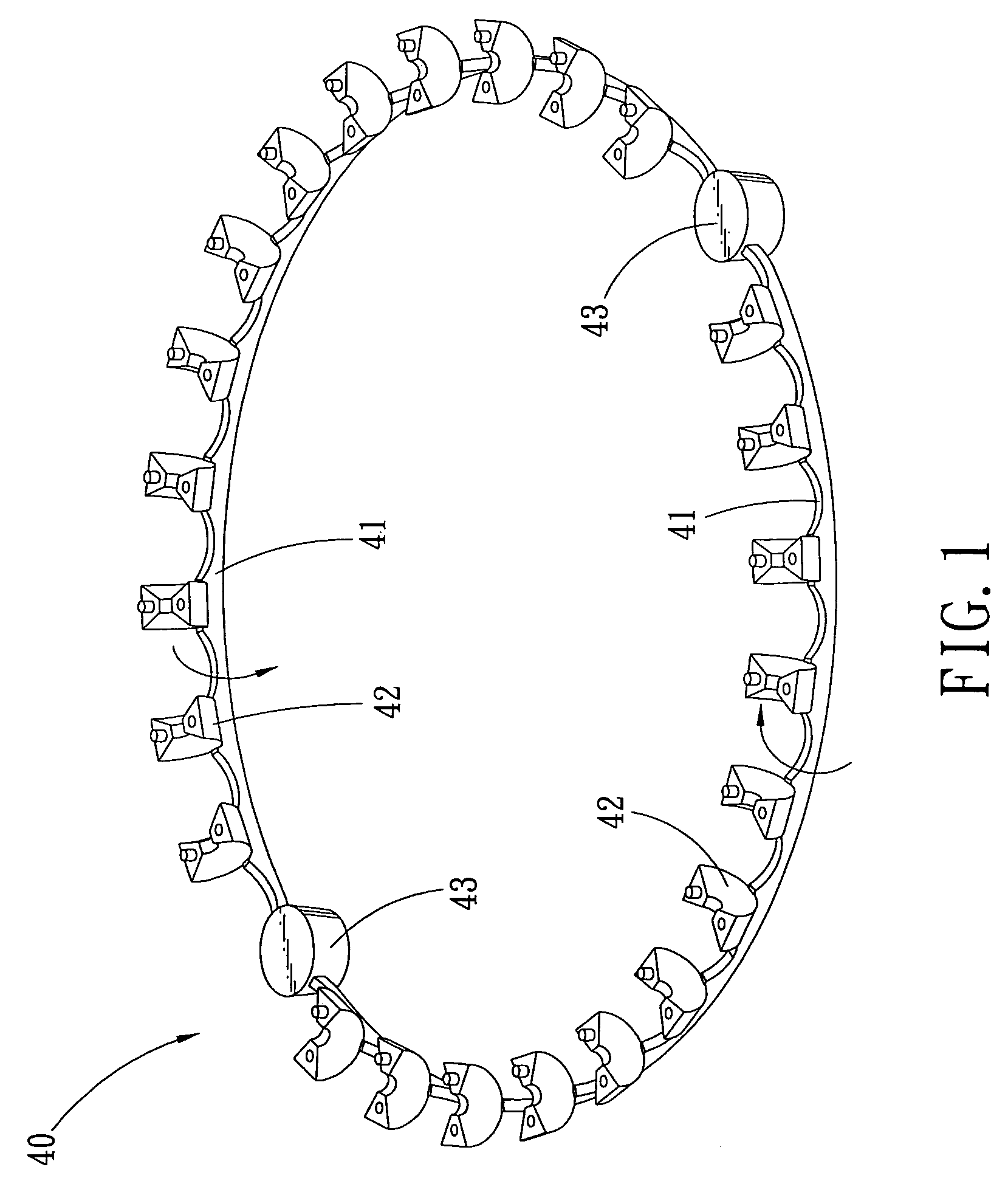
[0021]Referring to FIG. 1, wherein a ring-shaped retaining device for rolling-element is shown in accordance with a first embodiment of the present invention, here the rolling-elements (not shown) of the retaining device 40 are using balls as example. Wherein the retaining device 40 is a ring structure that is formed by partitions 42 which are linked together by link-belt 41. The link-belt 41 is additionally provided with end-part 43 respectively at its both ends, so as to firmly retain the rolling elements in the retaining device 40. When installing rolling-elements into the retaining device 40, the retaining device 40 should be turned inward, and then install the rolling-elements sequentially, so as to form a complete retaining device for rolling-elements.

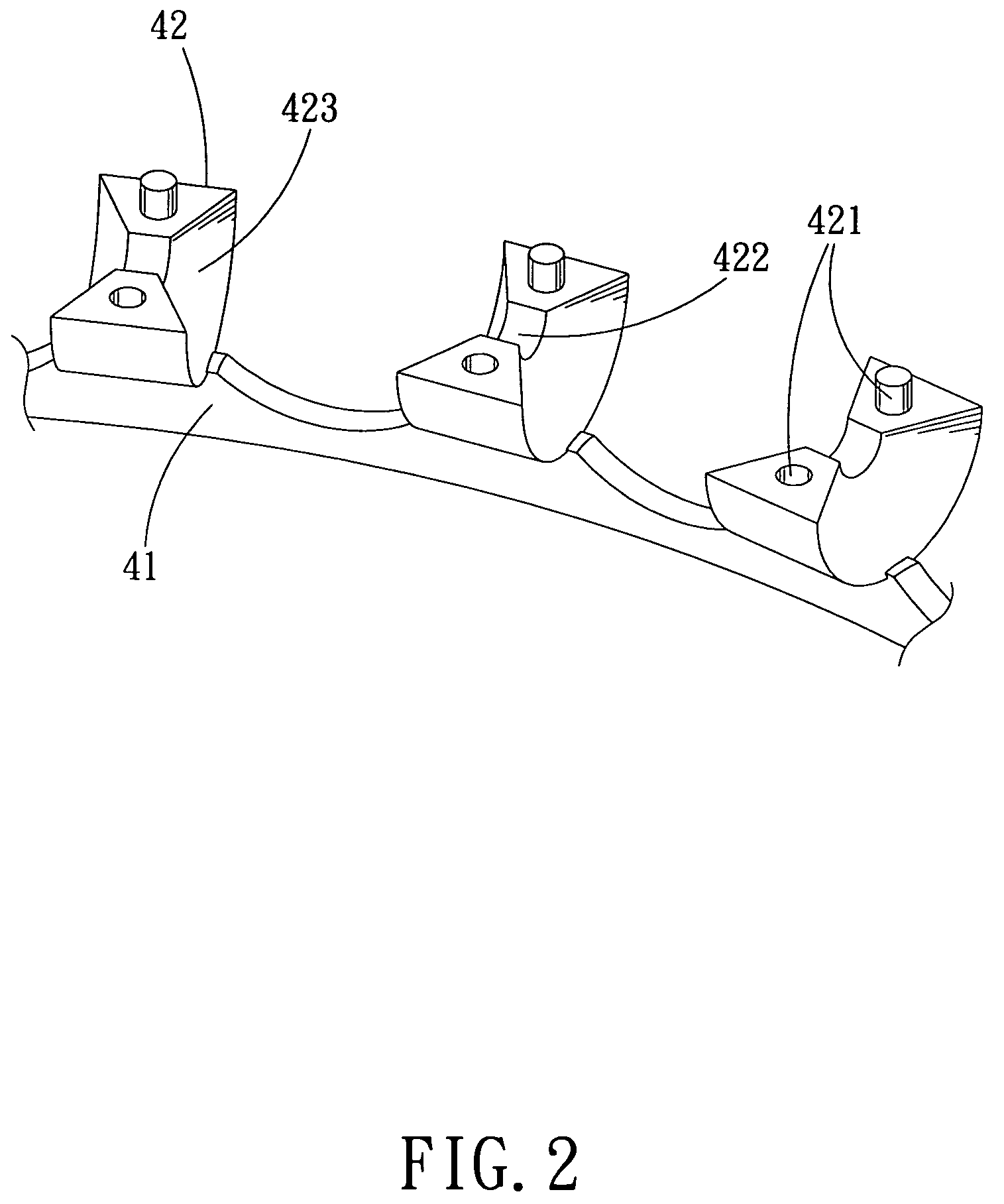
[0022]FIG. 2 is a partial amplified view of the retaining device for rolling-elements of FIG. 1. It can be seen from the drawing that each partition 42 on the link-belt 41 is provided at its jointing portion with an engaging port...


PUM


Abstract

A retaining device for rolling-element includes the partition and the link-belt. The characteristic of the retaining device for rolling-element is that the partition is linked to form a ring by the link-belt, then the ring is turned in to form a space for retaining the rolling-element, so as to reduce the friction of the rolling-element.

Description

BACKGROUND OF THE INVENTION[0001]1. Field of the Invention[0002]The present invention relates to a retaining device for rolling-element, and more particularly to a retaining device for rolling-element which is applied to linear transmission unit.[0003]2. Description of the Prior Arts[0004]The linear transmission units of prior arts generally can be divided into two categories: First one is an independent individual retainer, and another one is a retainer made up of plural independent individuals. As shown in FIG. 4, wherein the slide block 11 is slidably mounted onto a rail, which is interiorly provided with a plurality of rolling-elements 20 and between every two neighboring rolling-elements 20 is provided with a single retainer 30 so as to prevent the rolling-elements 20 from striking with each other. It is time-consuming to assemble this linear transmission unit by alternatively inserting the rolling-element and single retainer in the slide block, furthermore, the retainers and t...

Claims


Application Information

Patent Timeline
Patent Type & Authority Patents(United States)
IPC IPC(8): F16C29/06F16C33/38
CPCF16C33/3825F16C29/0633
Inventor CHIN-PEI, WANGCHUN-LIANG, WU
Owner HIWIN TECH
Why Eureka
Try Eureka