
Methods and instruments for laparoscopic spinal surgery

Inactive Publication Date: 2007-02-20
SDGI HLDG
View PDF49 Cites 68 Cited by
  • Summary
  • Abstract
  • Description
  • Claims
  • Application Information

AI Technical Summary

Benefits of technology

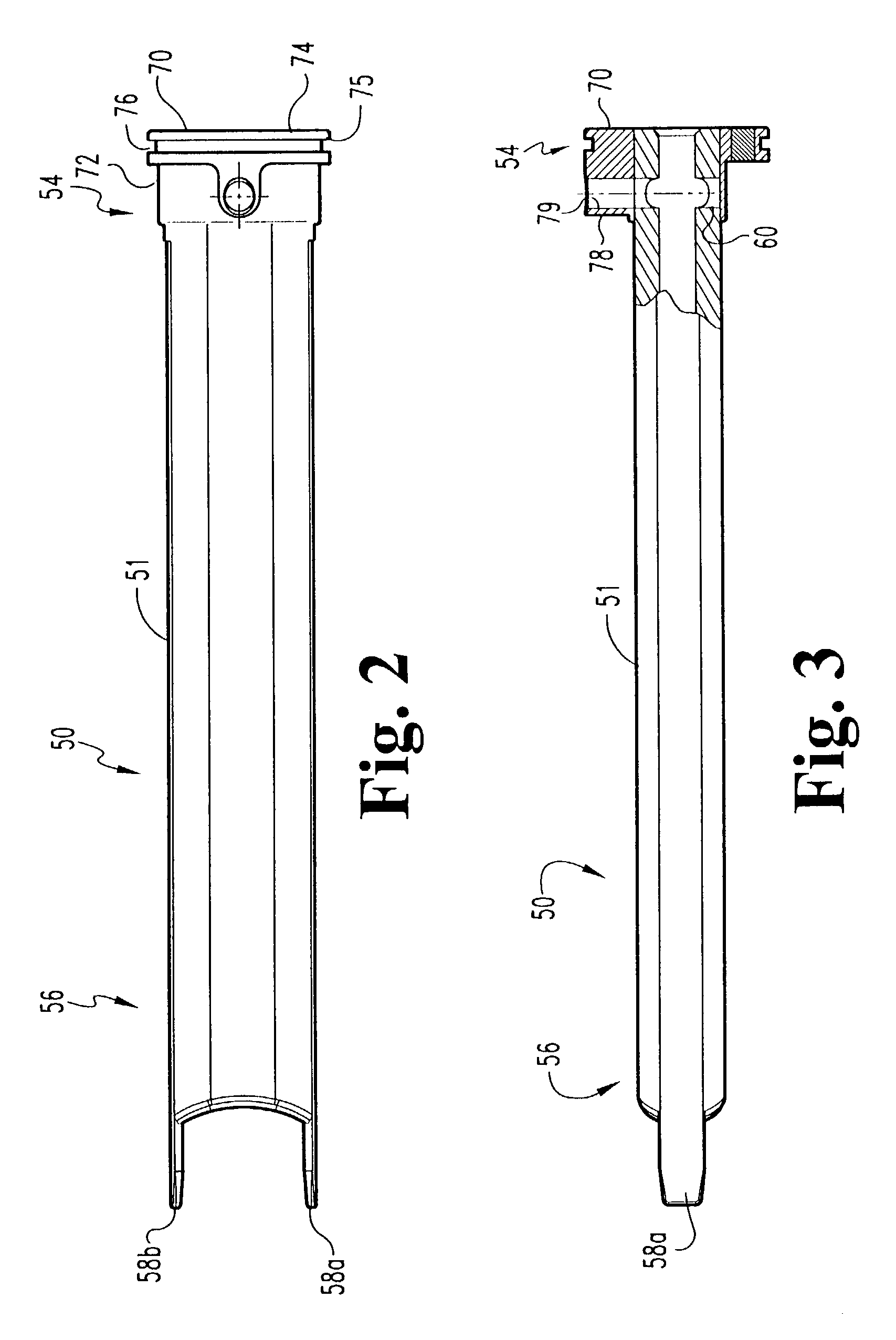
[0009]According to another aspect of the invention, an apparatus for performing a surgical procedure in the disc space between adjacent vertebrae of a patient is provided. The apparatus includes a sleeve having a distal end, an opposite proximal end, and a sealable working channel extending therethrough. The working channel has a first portion and an adjacent second portion each configured to receive surgical instruments therethrough. A cap member is secured to the second end of the sleeve. The cap member has an access port that seals the working channel when closed. The access port is alignable with a corresponding one of the first or second portions. The cap member can be moved with respect to the sleeve to substantially align the access port with the other of the first and second portions while the working channel remains sealed.
[0010]According to another aspect of the invention, an apparatus for performing a surgical procedure in the disc space between adjacent vertebrae of a patient is provided. The apparatus has a sleeve with a distal end, an opposite proximal end, and a working channel extending therebetween. The sleeve has a non-circular perimeter

Problems solved by technology

The techniques and instruments of the '666 publication suffer from the disadvantage of requiring multiple manipulations of vessels and tissue adjacent the vertebral bodies to perform the procedure.
Multiple manipulation of the vessels and tissues may increase the overall time of the procedure and increase the risk of damage to the vessels.

Method used


Image

  • Methods and instruments for laparoscopic spinal surgery
  • Methods and instruments for laparoscopic spinal surgery
  • Methods and instruments for laparoscopic spinal surgery

Examples


Embodiment Construction

[0055]For the purposes of promoting an understanding of the principles of the invention, reference will now be made to the embodiment illustrated in the drawings and specific language will be used to describe the same. It will nevertheless be understood that no limitation of the scope of the invention is thereby intended. Any such alterations and further modifications in the illustrated devices, and any such further applications of the principles of the invention as illustrated herein are contemplated as would normally occur to one skilled in the art to which the invention relates.

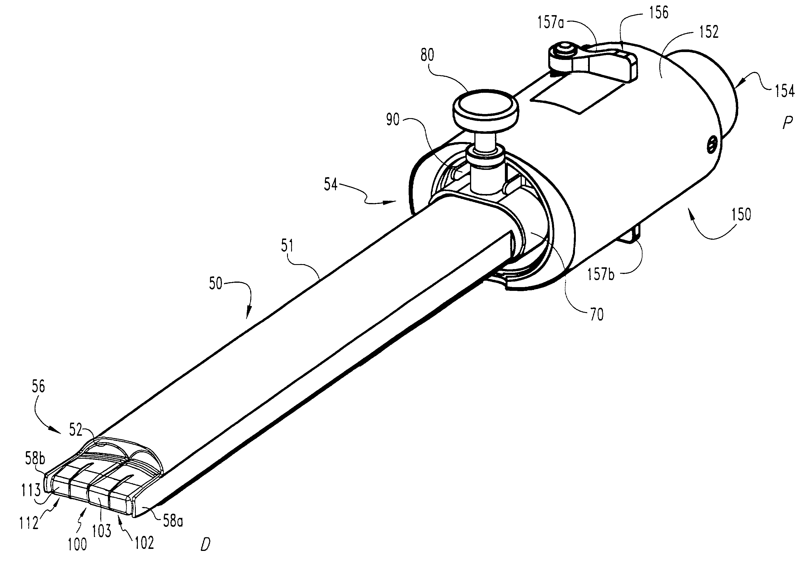
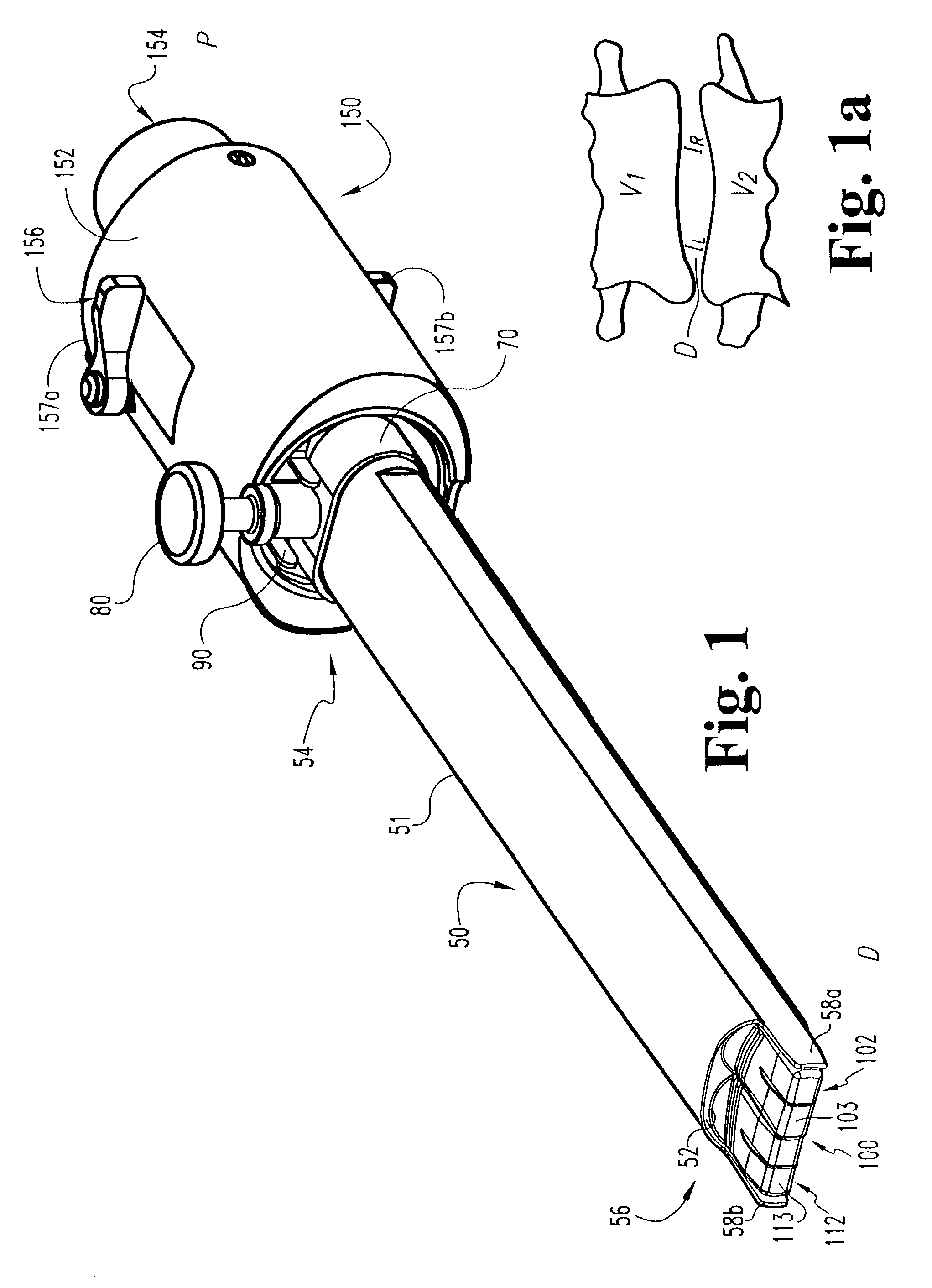
[0056]A surgical instrument assembly in accordance with the present invention is illustrated in FIG. 1 and designated generally at 45. Surgical instrument assembly 45 is particularly useful for accessing and preparing, as show in FIG. 1a, a disc space S for insertion of vertebral implants or fusion devices between upper vertebral body V1 and lower vertebral body V2. In one aspect of the present invention, ...


PUM


Abstract

Surgical techniques and instruments are provided for performing surgical procedures in a disc space. The instrument includes a sleeve having a distal end and an opposite proximal end and a working channel extending therebetween. The working channel includes a first portion and an adjacent second portion configured to receive surgical instruments therethrough. A cap member is secured to the sleeve at the proximal end. The cap member has a sealable access port substantially aligned with a corresponding one of the first or second portions. The cap member is movable with respect to the sleeve to substantially align the access port with the other of the first and second portions while the working channel remains sealed. Various techniques using various surgical instruments in laparoscopic procedures are also disclosed.

Description

CROSS-REFERENCE TO RELATED APPLICATION[0001]This application is a divisional of U.S. patent application Ser. No. 09 / 525,972 filed on Mar. 15, 2000, and now issued as U.S. Pat. No. 6,514,260 and which is incorporated herein by reference in its entirety.BACKGROUND OF THE INVENTION[0002]The present invention relates generally to methods and instruments for performing spinal surgery. Specifically, the invention concerns laparoscopic techniques and instruments to perform spinal surgeries.[0003]The use of surgical techniques to correct the causes of low back pain, such as spinal injuries and deformities, has steadily increased over the last several years. One common procedure for relieving pain from the above-described problems is a discectomy, or surgical removal of a portion or all of an intervertebral disc, followed by implantation of a device between the adjacent vertebrae, such as a vertebral implant or fusion device. Typically, implantation of such a device is intended to promote bo...

Claims


Application Information

Patent Timeline
IPC IPC(8): A61B17/58A61F2/44A61B17/56A61B17/02A61B17/16A61B17/17A61B17/34
CPCA61B17/1757A61B2017/3445A61B2017/0256A61B17/3462
Inventor ZDEBLICK, THOMASMCGAHAN, THOMAS V.DERIDDER, STEVEN D.
Owner SDGI HLDG
Learn More