Low switching frequency power factor correction circuit

a power factor and low switching frequency technology, applied in the direction of electric variable regulation, process and machine control, instruments, etc., can solve the problems of complex and expensive power electronic circuitry, inability to adjust the output voltage, etc., to achieve good output voltage regulation

Active Publication Date: 2007-02-20
INFINEON TECH AMERICAS CORP
View PDF1 Cites 60 Cited by
  • Summary
  • Abstract
  • Description
  • Claims
  • Application Information

AI Technical Summary

Benefits of technology

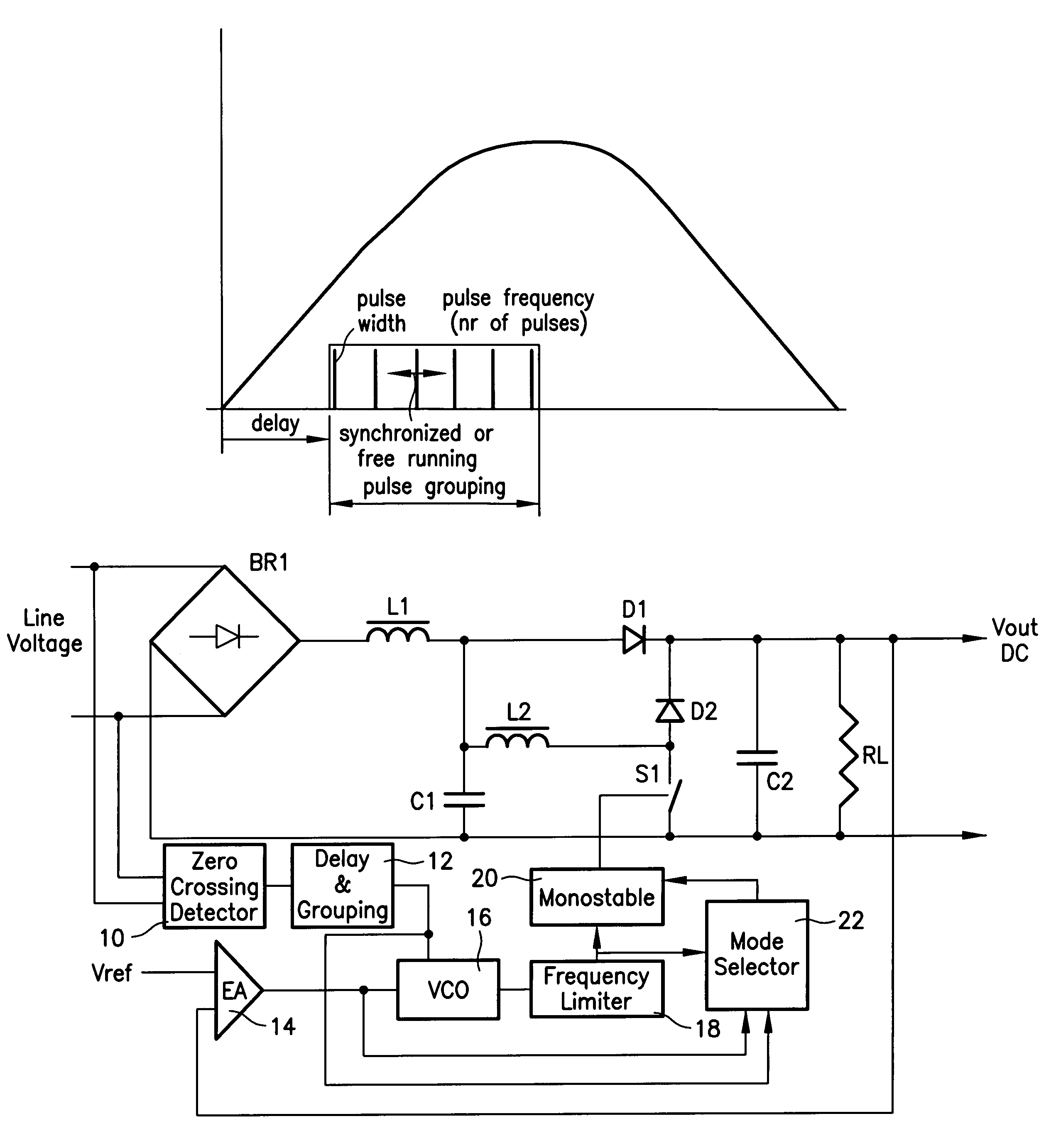
[0021]It is therefore a primary objective of the invention to provide a method for limiting the harmonics of the line current by using a low switching frequency harmonic correction circuit (HCC), which only transmits a part of the total power drawn by the equipment to be fed, and which is able to provide good line and load regulation of the output DC voltage which feeds the equipment.
[0025]The circuit is able to achieve good regulation of the output voltage versus both load and line variations in a large range, while keeping harmonics of the line current below limits imposed by International Regulations (mainly European EN61000-3-2 for Class A equipment). The circuit is also able to generate an auxiliary power supply which may be needed by the controller for the correction circuit itself and by other equipment or power stages which are fed by the correction circuit.

Problems solved by technology

However, any time a non linear load (like an input rectifier bridge followed by a filtering capacitor) is applied to the AC line, such load produces a distortion of the line current from being sinusoidal and in phase with the line voltage.
Such topology is able to shape the input line current to be substantially sinusoidal and in phase with the line voltage, and is able to regulate quite well the output DC voltage versus load (the power drawn by the equipment) and line variations, but has the following drawbacks:a) complex and expensive power electronic circuitry is required;b) high frequency operation generates high frequency EMI;c) the circuitry acts as a “series” connected active filter in between the rectified line voltage and the equipment to be fed, thereby transmitting all the power drawn by the equipment; andd) due to that, and due to the high frequency operation, the boost PFC introduces power losses which, often, are not negligible with respect to the total power losses of the equipment to be fed.
On the other hand, cost sensitive applications which handle limited amounts of power (below 1 HP) try to avoid the use of such expensive active PFC methods and only use passive filters (usually inductors) in series with the line (before or after the rectifying bridge) at the input of the equipment.
Such “passive” filters, have several drawbacks:a) they are bulky (and sometime expensive);b) they also transmit all the power consumed by the equipment, so dissipate significant power;c) they constitute a series impedance at the equipment's input, thereby reducing the DC voltage available at the equipment itself; furthermore, the voltage drop generated by such series impedance changes with the load.
Finally, such methods generally provide quite good regulation of the output voltage of the filter stage versus load, but, when the auxiliary switch is being driven only once for every line half period as described in the paper, have the general drawback that regulation of the output voltage versus the input (line) voltage variations is very poor.
Such low voltage supply is usually derived by a dedicated circuit (very often a flyback switching power supply directly fed by the rectified line but sometimes a step-down switching regulator) which adds a significant cost to the whole power conversion chain, and, by switching at high frequency, introduces other EMI.
In other cases, a simple resistive drop is used, which dissipates much more power than the power it actually delivers to the housekeeping circuitry.

Method used


Image

  • Low switching frequency power factor correction circuit
  • Low switching frequency power factor correction circuit
  • Low switching frequency power factor correction circuit

Examples


Embodiment Construction

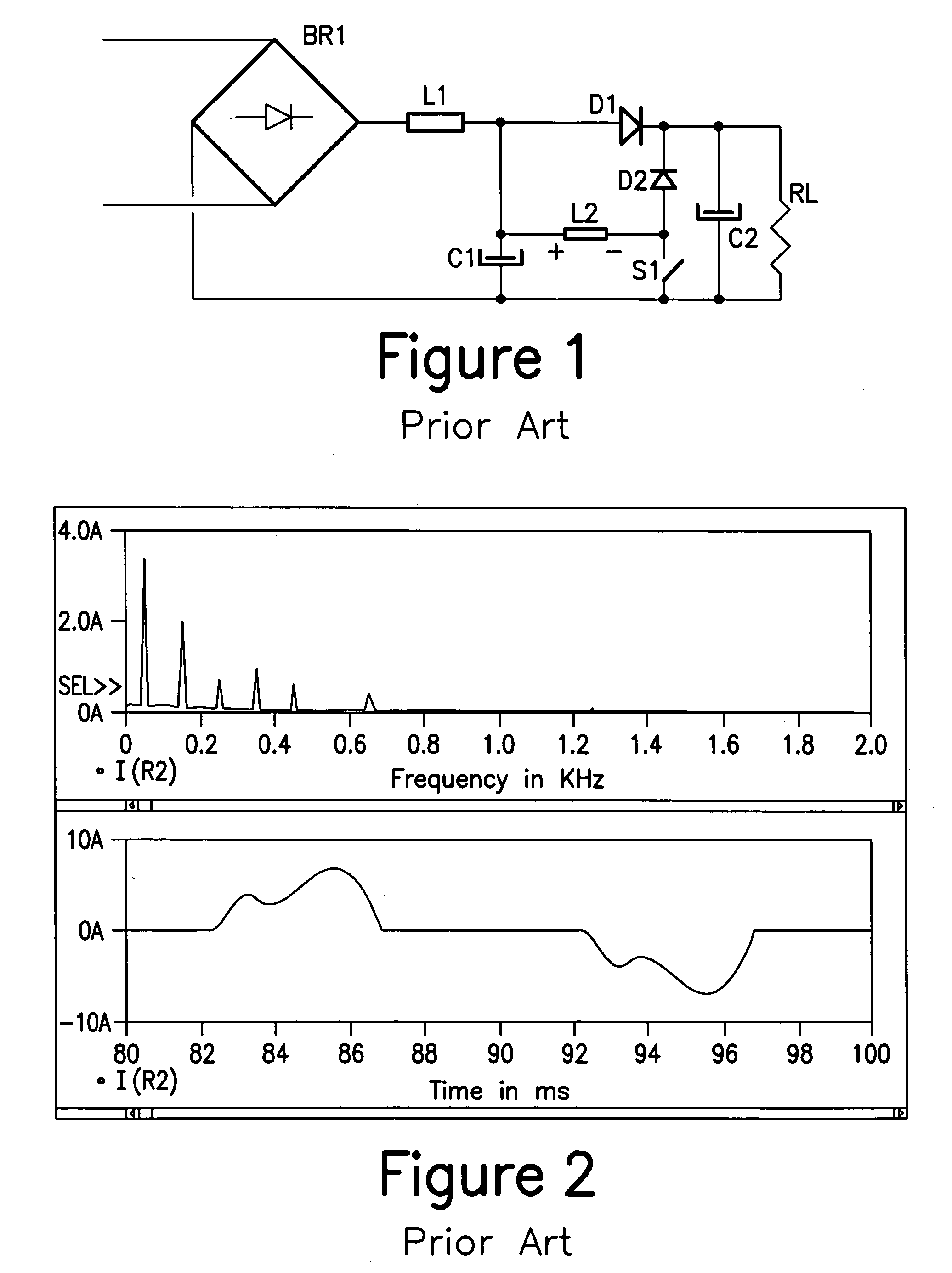
[0037]In FIG. 1, which is a prior art circuit, RL represents the equipment to be fed (very often a further power conversion stage) as the “equivalent” load to the harmonic correction (or power factor correction) circuit. The harmonic correction circuit comprises L1,C1,L2,S1, D1 and D2, while C2, together with BR1, represent the standard rectifying and filtering stage which, alone, would produce substantial distortion of the line current. In FIG. 1, the housekeeping power supply is not shown.

[0038]Referring to FIG. 1, it is clear that the circuit of FIG. 1 has several “degree of freedom” with respect to how the switch S1 can be driven ON and OFF during each line half-period.

[0039]Firstly, the modulation of switch S1 has to be the same for subsequent line half periods. In-fact, if it were different between two subsequent half line periods, the line current would become rich in even harmonics, whose regulation limits are much more stringent than for odd harmonics.

[0040]Given this const...


PUM


Abstract

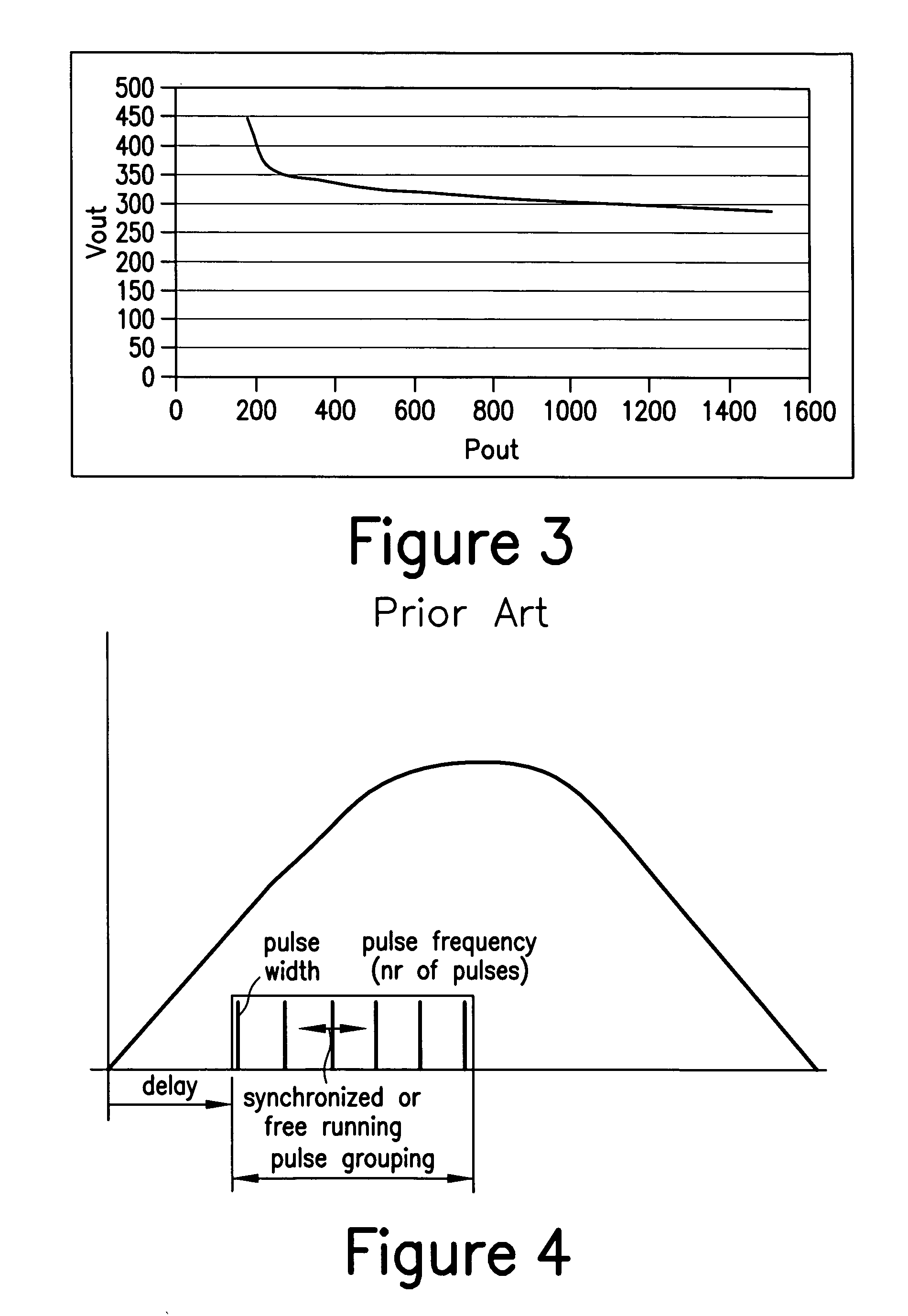
A power factor correction circuit for driving a switch of a boost type converter circuit having an AC line frequency input, comprising a sense circuit for sensing and comparing the output voltage of the boost type converter circuit to a reference voltage, a circuit responsive to the output of the sense circuit for providing a drive signal for driving the switch, wherein the drive signal comprises a pulsed signal comprising a pulse grouping during each half cycle of the AC line frequency comprising at least one pulse wherein the number of pulses and frequency of the pulses of the pulse grouping changes with the output of the sense circuit up to a threshold value with the pulse width of the pulses being substantially constant; and when the output of the sense circuit has reached the threshold value, the pulse width of the pulses of the pulse grouping are varied in accordance with the output of the sense circuit.

Description

CROSS REFERENCE TO RELATED APPLICATIONS[0001]This application claims the benefit and priority of U.S. Provisional patent application Ser. No. 60 / 642,826 filed Jan. 11, 2005 entitled LOW SWITCHING FREQUENCY POWER FACTOR CORRECTION CIRCUIT, U.S. Provisional patent application Ser. No. 60 / 638,125 filed Dec. 22, 2004 entitled LOW SWITCHING FREQUENCY POWER FACTOR CORRECTION CIRCUIT, and U.S. Provisional patent application Ser. No. 60 / 578,010 filed Jun. 7, 2004 entitled LOW SWITCHING FREQUENCY POWER FACTOR CORRECTION CIRCUIT, the entire disclosures of which are incorporated herein by reference.BACKGROUND OF THE INVENTION[0002]The present invention relates to power factor correction (PFC) methods and circuits. PFC circuits are known in the literature and are applied in a broad range of electronic equipment, ranging from lighting ballast circuits, to switch mode power supplies, to motor drives.[0003]Such types of equipment generally require a direct current (DC) input voltage to operate pro...

Claims


Application Information

Patent Timeline
Patent Type & Authority Patents(United States)
IPC IPC(8): G05F1/70H02M1/42
CPCH02M1/4208H02M1/4225Y02B70/126Y02B70/10
Inventor BOCCHIOLA, CESAREGRASSO, MASSIMOIT), TAKAHASHI, TOSHIO
Owner INFINEON TECH AMERICAS CORP
Why Eureka
Try Eureka