Antenna with power matching circuit

a technology of power matching and antenna, which is applied in the direction of resonant antennas, antenna adaptation in movable bodies, disturbance protection, etc., can solve the problems of poor rf conductors between the conventional point-of-contact connectors and the problem of the connection between the radiator and the antenna leads remains. , to achieve the effect of effective balance of current distribution and impedance in conductive elements

Active Publication Date: 2007-02-20
R A MILLIER IND INC
View PDF8 Cites 16 Cited by
  • Summary
  • Abstract
  • Description
  • Claims
  • Application Information

AI Technical Summary

Benefits of technology

[0007]According to the invention, a mobile antenna includes a center-fed, broadband, dipole radiator, and a coupler assembly for mounting the dipole radiator to a mount. A power matchin

Problems solved by technology

One problem has been noted at higher frequencies, however.
Conventional point-of-contact connectors between the radiator and the leads from the antenna are not good RF conductors.
But problems remain in known mobi

Method used


Image

  • Antenna with power matching circuit
  • Antenna with power matching circuit
  • Antenna with power matching circuit

Examples


second embodiment

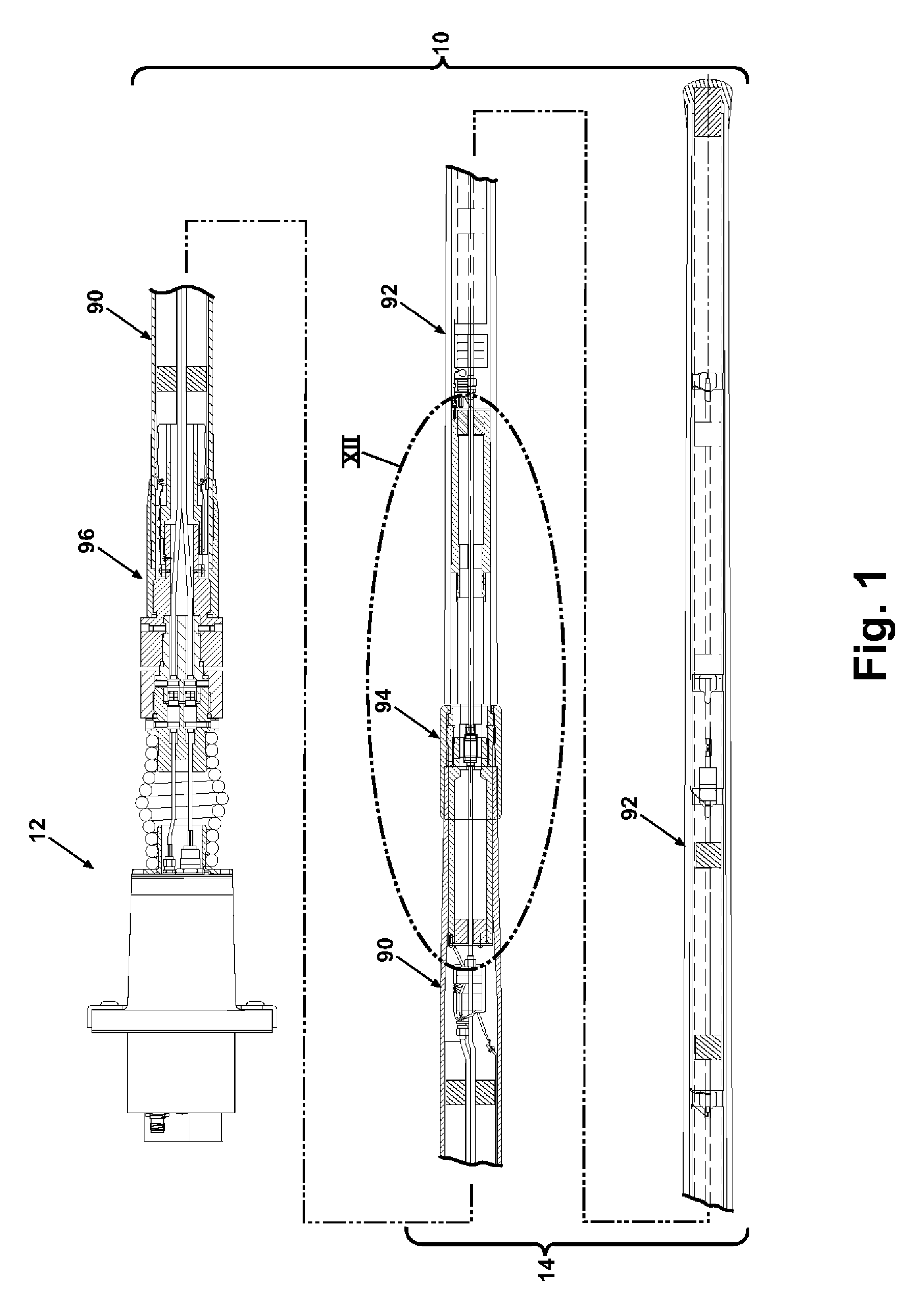
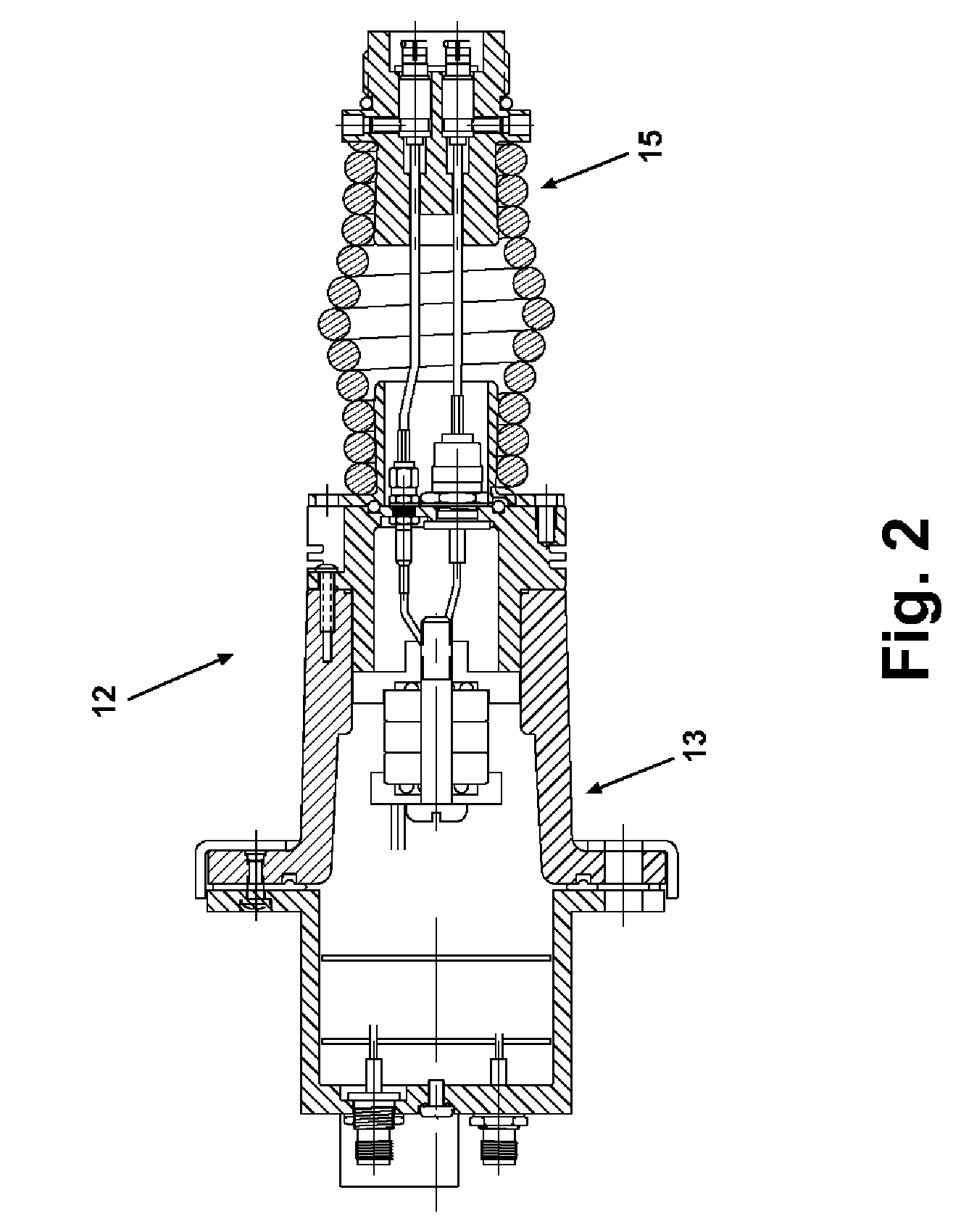
[0062]a multiband antenna 300 according to the invention is shown in FIGS. 18–24. The antenna 300 comprises a mount assembly 302 and a whip assembly 304. The mount assembly 302 comprises a base housing 306 with an annular mounting flange 308, a base connector 310, a spring plate 312, a barrel spring 314, and an upper spring holder 316. The base housing 306 in this embodiment is conventional, adapted to mount to a vehicle (not shown) by bolts through apertures in the annular mounting flange 308.

[0063]Looking now at FIGS. 19–21, the base connector 310 comprises a hollow cylindrical body portion 318 that is covered at one end by a plate 320 centered on the longitudinal axis 322 of the body portion. The plate 320 has several apertures 324 at its periphery and the base connector 310 has three receptacles 326. The receptacles 326 are sealed against moisture.

[0064]The spring plate 312 is fixedly mounted to the spring 314 and bolted to the base connector plate 310, and has a central apertur...

first embodiment

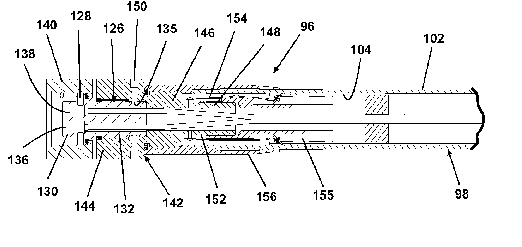
[0067]It will be understood that the physical structure of the electrical elements 366, 368 is similar to that in the first embodiment above, i.e., one or more transmission lines centered within a dielectric tube, wrapped with a conductive sleeve of copper or aluminum, all encased by a fiberglass housing. The lower electrical element 366 thus comprises a conductive sleeve 372 and three transmission lines 383, 384, and 385. The upper electrical element 368 comprises five conductive sleeves 396, 397, 398, 400, and 402, with one or two of the transmission lines 384, 385 centered therein. The transmission line 383 is a coaxial cable servicing the 30–175 MHz range. The transmission lines 384, 385 are also coaxial cables servicing the 225–450 MHz and 500–1000 MHz ranges, respectively. All of the transmission lines 383, 384, and 385 are centered within the conductive sleeves 372, 396, 397, 398, 400, and 402 by spacers 392.

[0068]At a lower end of the lower physical portion 360 is a male con...


PUM


Abstract

A mobile antenna includes a center-fed, broadband, dipole radiator, and a coupler assembly for mounting the dipole radiator to a mount. A power matching circuit is connected between the dipole radiator and the coupler assembly to maintain an effective balance of current distribution and impedance in conductive elements of the antenna.

Description

CROSS REFERENCE TO RELATED APPLICATION[0001]This application claims the benefit of U.S. application Ser. No. 60 / 481,534 filed Oct. 21, 2003.FIELD OF THE INVENTION[0002]The invention relates to high power, mobile antennas that can transmit and / or receive in one or more frequency bands.DESCRIPTION OF THE RELATED ART[0003]It is known to isolate reception on a mobile antenna for vehicles in the 30–88 MHz range by a combination of coaxial cable at a lower end of the antenna and a dipole formed of a linear wire radiator at an upper end of the antenna. The length of such an antenna requires that it be broken down for easy transport. A mating connector at the point where the coaxial cable connects to the wire enables such a break, even though the feed point for the dipole is not at the break. In other words, the break occurs in one of the radiators of the dipole.[0004]A similar structure is also known for NTDR (near term digital radio) antennas in the 225–450 MHz range. One problem has been...

Claims


Application Information

Patent Timeline
IPC IPC(8): H01Q9/16
CPCH01Q1/002H01Q1/1214H01Q1/3275H01Q5/40H01Q9/18H01Q5/25H01Q5/321H01Q5/00
Inventor BOGDANS, PAUL A.SEWARD, GLEN J.PLATT, JOHN JEREMY CHURCHILL
Owner R A MILLIER IND INC
Why Eureka
Try Eureka