Apparatus for stereoscopic photography

a technology for stereoscopic photography and apparatus, applied in the direction of optics, electrical apparatus, instruments, etc., can solve the problems of affecting the quality of the perceived three-dimensional image, affecting the quality of the perceived image, so as to achieve the effect of improving the quality of the perceived three-dimensional imag

Inactive Publication Date: 2007-02-20
PERISIC ZORAN
View PDF5 Cites 21 Cited by
  • Summary
  • Abstract
  • Description
  • Claims
  • Application Information

AI Technical Summary

Benefits of technology

[0030]An identical apparatus attached to the front of a camera lens and placed in the position of the viewer in correct alignment along the corresponding axes of the projection apparatus will be able to record the left and the right eye images reflected from the auto-collimating front-projection screen simultaneously. Moreover, a subject placed in front of the front projection screen within the field of view of the apparatus and lit appropriately will be recorded as a three-dimensional composite image, i.e. it will be seen by the camera as being inside the projected image. This can be particularly effective when the stereoscopic projected image has some foreground elements and the “subject” is placed at middle distance. Front-projection is an established technique for creating visual effects composites in conventional monocular image recording.
[0035]Another advantage of the apparatus of the present invention is that the camera lens does not compound the spherical aberrations of the recorded images, because the left and right eye images are recorded as head-to-head or toe-to-toe images and, as such, are affected equally by the spherical aberrations. Thus, when the two images are superimposed for viewing they effectively cancel one another. The quality of the perceived three-dimensional image is therefore improved.

Problems solved by technology

However, in the case of the “over-under” method, where a single projection lens and additional optical arrangements are used to project both images the projection arrangement has a detrimental effect that the optical distortions introduced by the optical elements, mainly spherical aberrations tend to be exaggerated when the two images are superimposed onto each other for viewing.
A perfect match between the two images is not possible on projection because each image is affected differently by the spherical aberrations of the projection lens since both images are part of the same image circle, i.e. the top corners of the upper image really match the bottom corners of the lower image instead of the corresponding corners.

Method used


Image

  • Apparatus for stereoscopic photography
  • Apparatus for stereoscopic photography
  • Apparatus for stereoscopic photography

Examples


Embodiment Construction

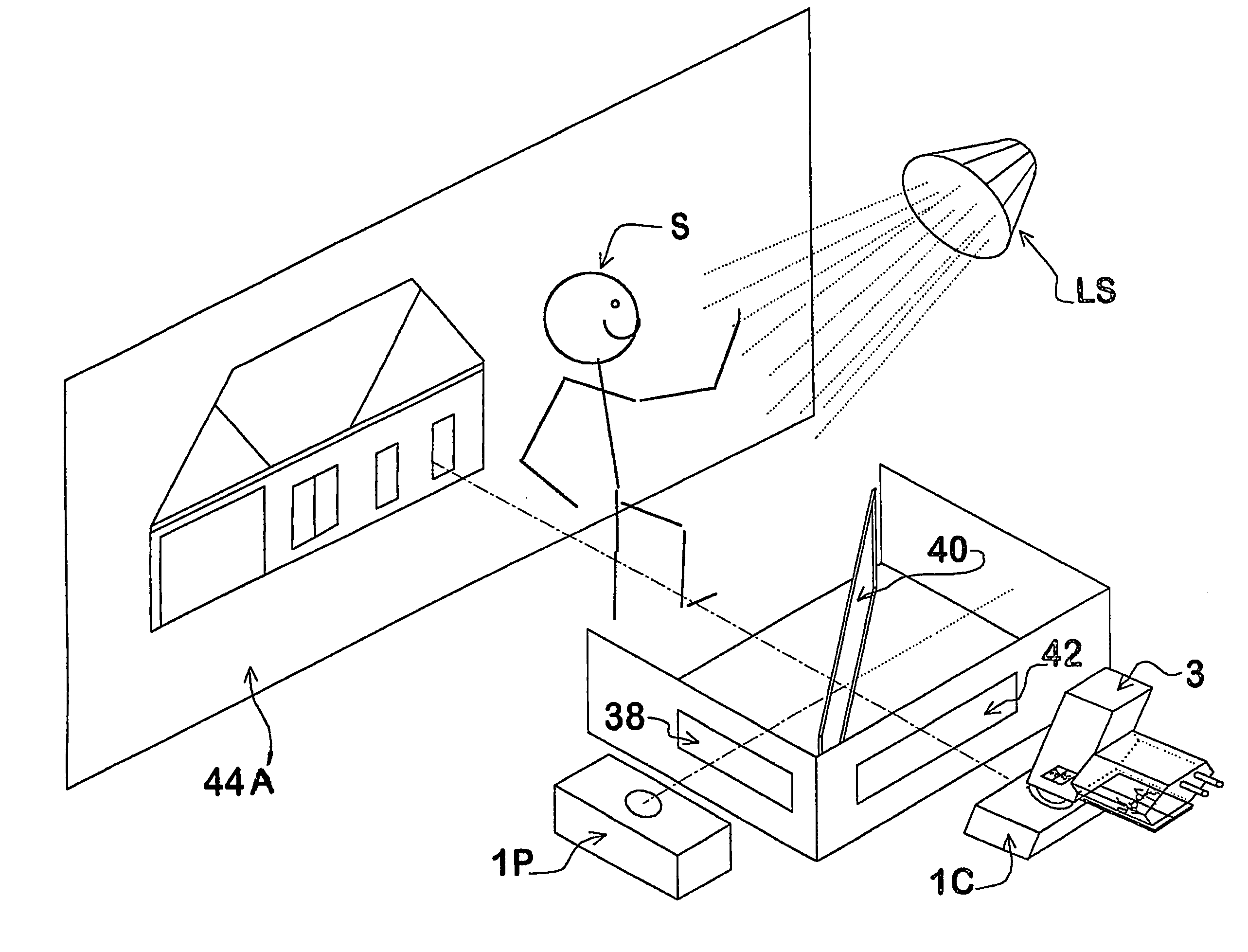
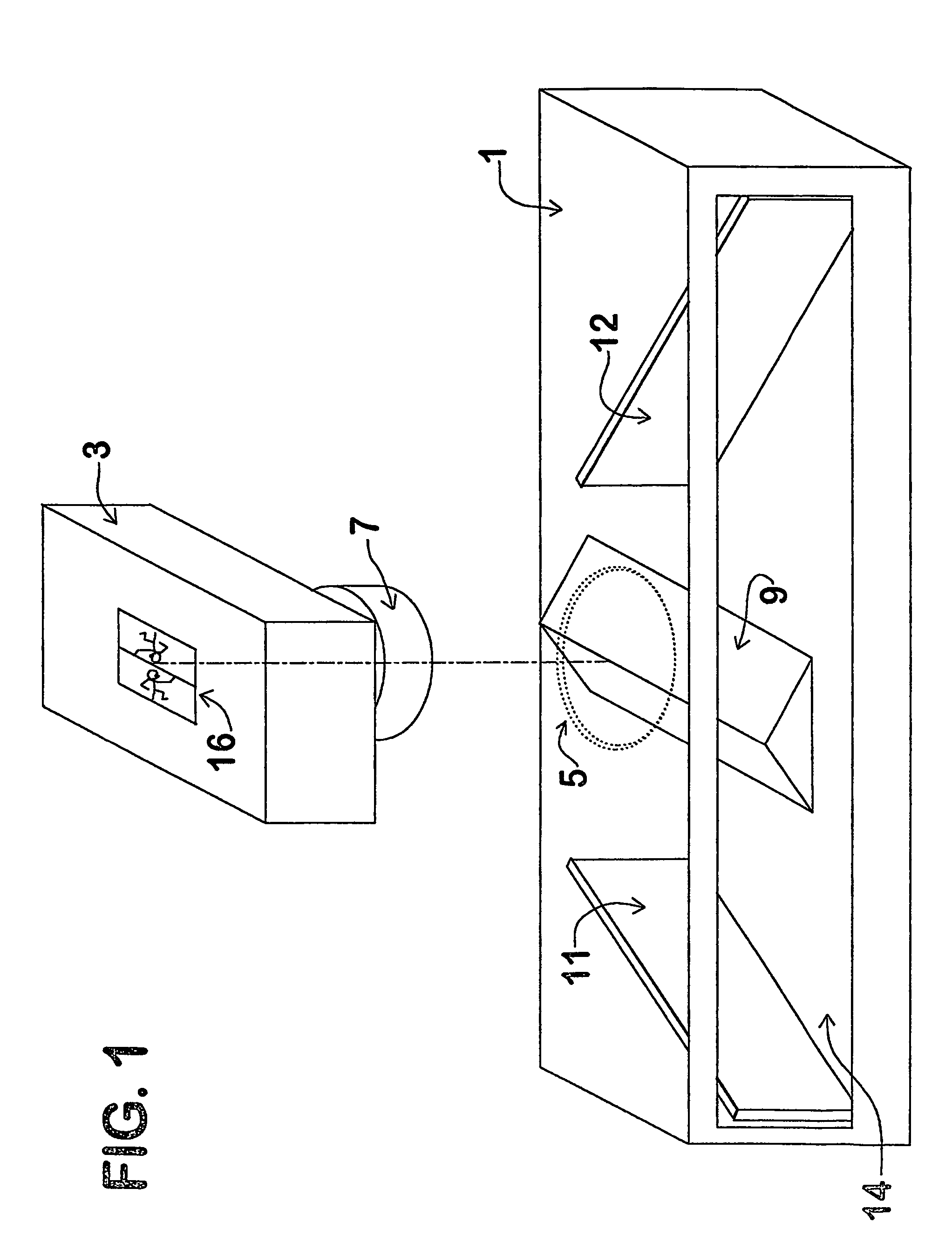
[0052]The apparatus 1 shown in FIG. 1 is arranged to be coupled to a conventional camera 3 by means of a coupling ring 5. The camera 3 may be a conventional 35 mm. camera or the like, or may equally be a video or cinematographic camera. The camera 3 has a lens 7 to which the coupling ring 5 of the apparatus 1 is attached, for example, utilising the screw thread provided on conventional camera lenses. Located along the axis of the camera lens 7 and coupling ring 5 is a triangular prism 9 arranged so that two of the prism faces are directed towards the camera lens 7. The prism faces are coated and act as front-surface plane mirrors. Alternatively small front-surface mirrors can be attached to the faces of the prism.

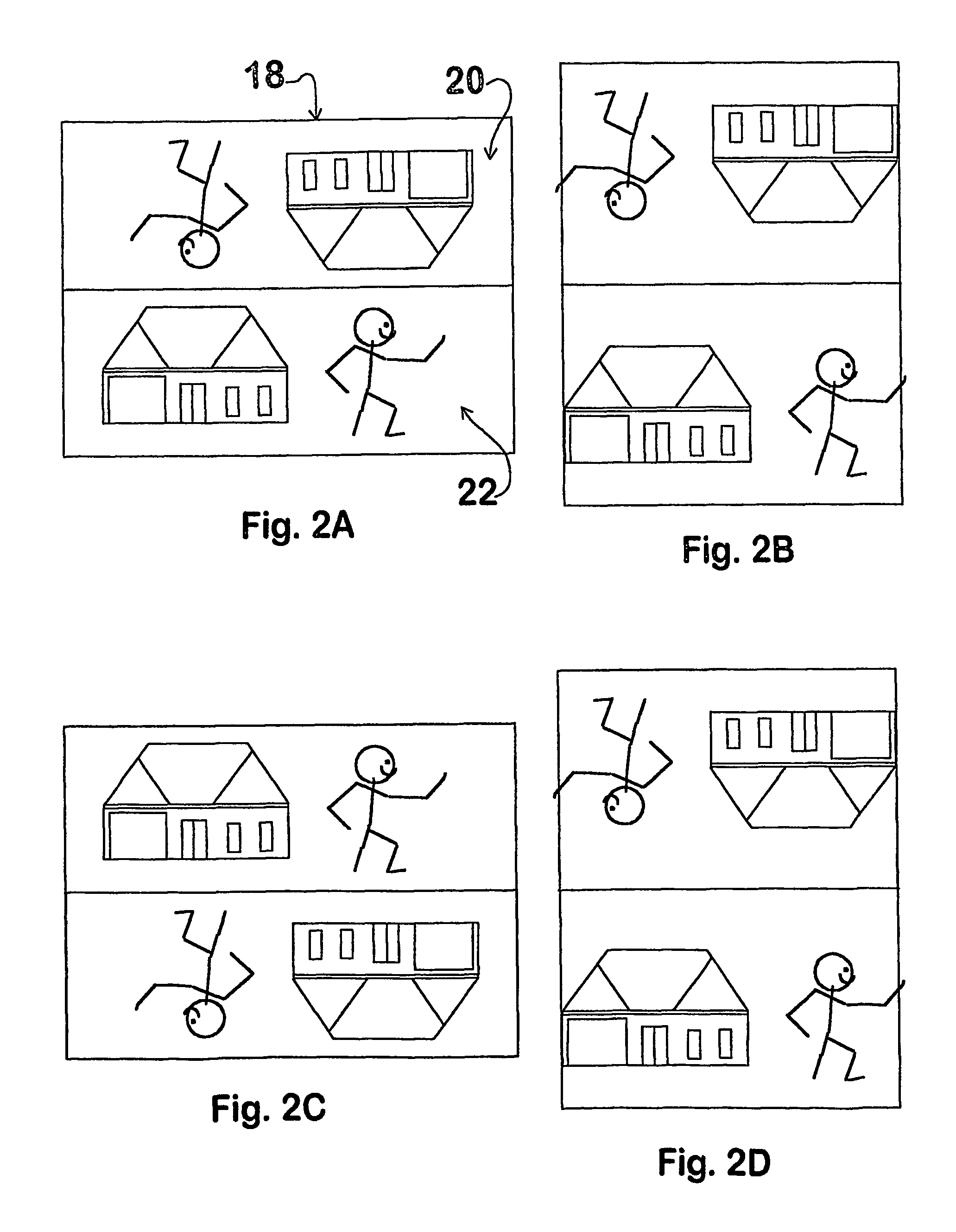
[0053]Located on the same plane as the triangular prism 9, and therefore at substantially 90° to the camera axis, are two plane mirrors 11 and 12. An aperture 14 is provided in the front face of the apparatus 1 through which light rays are received. The plane mirrors 11 and...


PUM


Abstract

An apparatus for providing left and right eye images along the axis of a single camera lens (7), the apparatus comprising optical means arranged to provide said left and right eye images (22, 20) as a pair of head-to-head or toe-to-toe images, i.e. with the two images (20, 22) separated by a center line and with either the tops of the two images (20, 22) or the bottoms of the two images (20, 22) adjacent the center line, so that the left and right eye images (22, 20) can be simultaneously recorded onto a single frame of a photographic film or other recording medium.

Description

FIELD OF THE INVENTION[0001]This invention relates to apparatus for providing and / or recording left and right eye images for three-dimensional photography, cinematography and / or videography and the means of viewing those images to produce a full stereoscopic effect.BACKGROUND OF THE INVENTION[0002]Three-dimensional photography is achieved by recording left and right eye views of a scene as two separate images. The left and right images are projected simultaneously onto a screen, typically one coated with a metallic surface. The separation between the two images is accomplished by means of polarizing filters placed in the projection beams of the left and right images with the polarizing axes set at 90  to each other and therefore cancelling each other. To ensure that each eye sees only the corresponding image the stereoscopic scene is viewed through glasses with polarizing filters whose polarizing axes are set at 90° to each other. The resultant stereoscopic image can be viewed in fu...

Claims


Application Information

Patent Timeline
Patent Type & Authority Patents(United States)
IPC IPC(8): G02B27/22H04N13/00
CPCH04N13/0217H04N13/0459H04N13/0055H04N13/021H04N13/0296H04N13/0434H04N13/0292H04N13/189H04N13/211H04N13/218H04N13/293H04N13/296H04N13/337H04N13/363
Inventor PERISIC, ZORAN
Owner PERISIC ZORAN
Why Eureka
Try Eureka