Capping head with a magnetic clutch

a technology of magnetic clutch and capping head, which is applied in the direction of caps, rotating screw stopper insertion, application, etc., can solve the problems that neither the adjustment scale on the outside surface of the magnetic clutch assembly, nor the adjustment scale on the outside surface of the upper spring assembly for adjusting the tension in the spring

Inactive Publication Date: 2007-02-27
PRECISION TORQUE CONTROL
View PDF10 Cites 27 Cited by
  • Summary
  • Abstract
  • Description
  • Claims
  • Application Information

AI Technical Summary

Problems solved by technology

In addition, none of the devices of the prior art have the capability of being able to read the adjustments scale on the outside surface of the magnetic clutch assembly, nor the adjustments scale on the outside surface of the upper spring assembly for adjusting the tension in the spring.

Method used


Image

  • Capping head with a magnetic clutch
  • Capping head with a magnetic clutch
  • Capping head with a magnetic clutch

Examples


Embodiment Construction

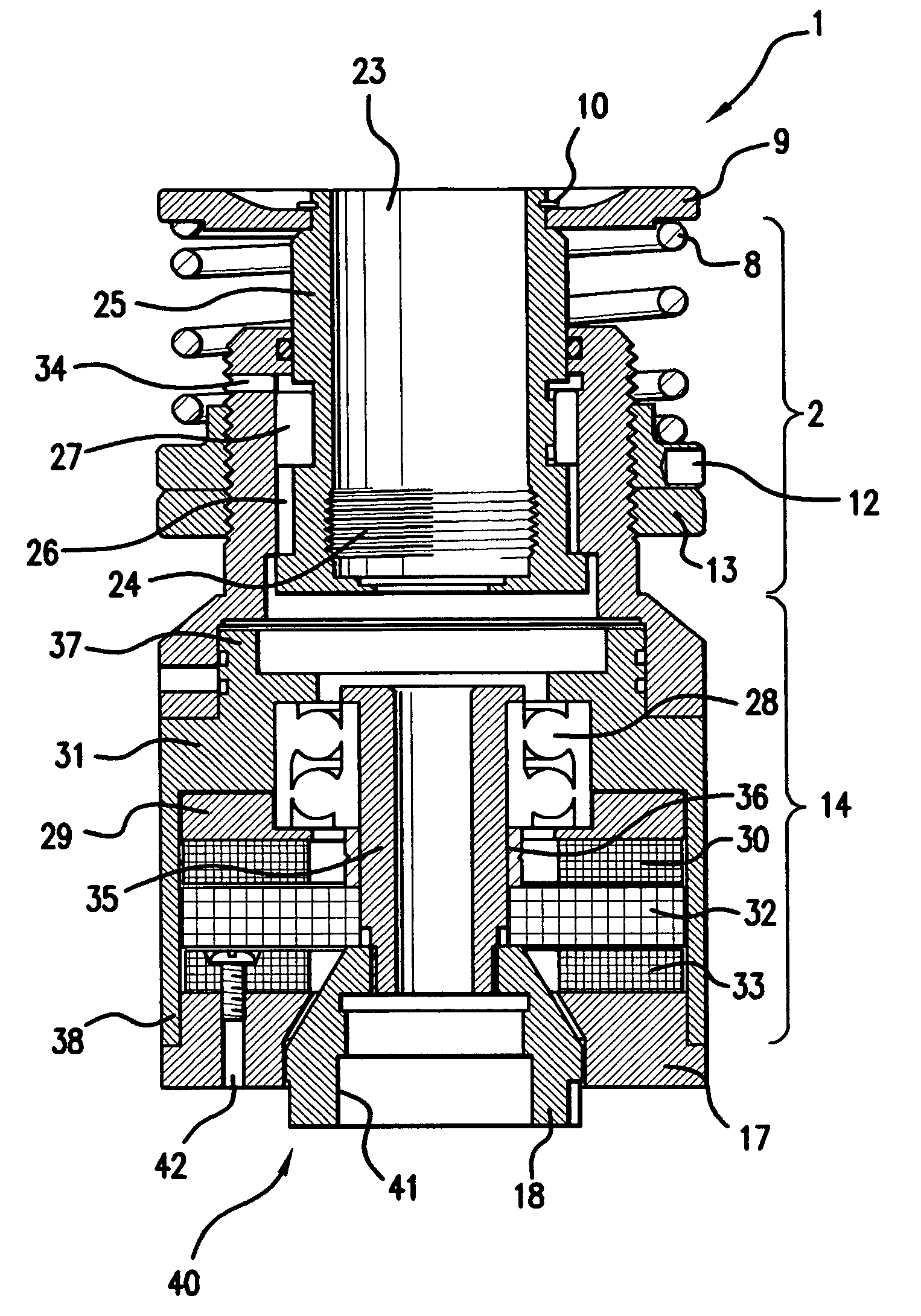
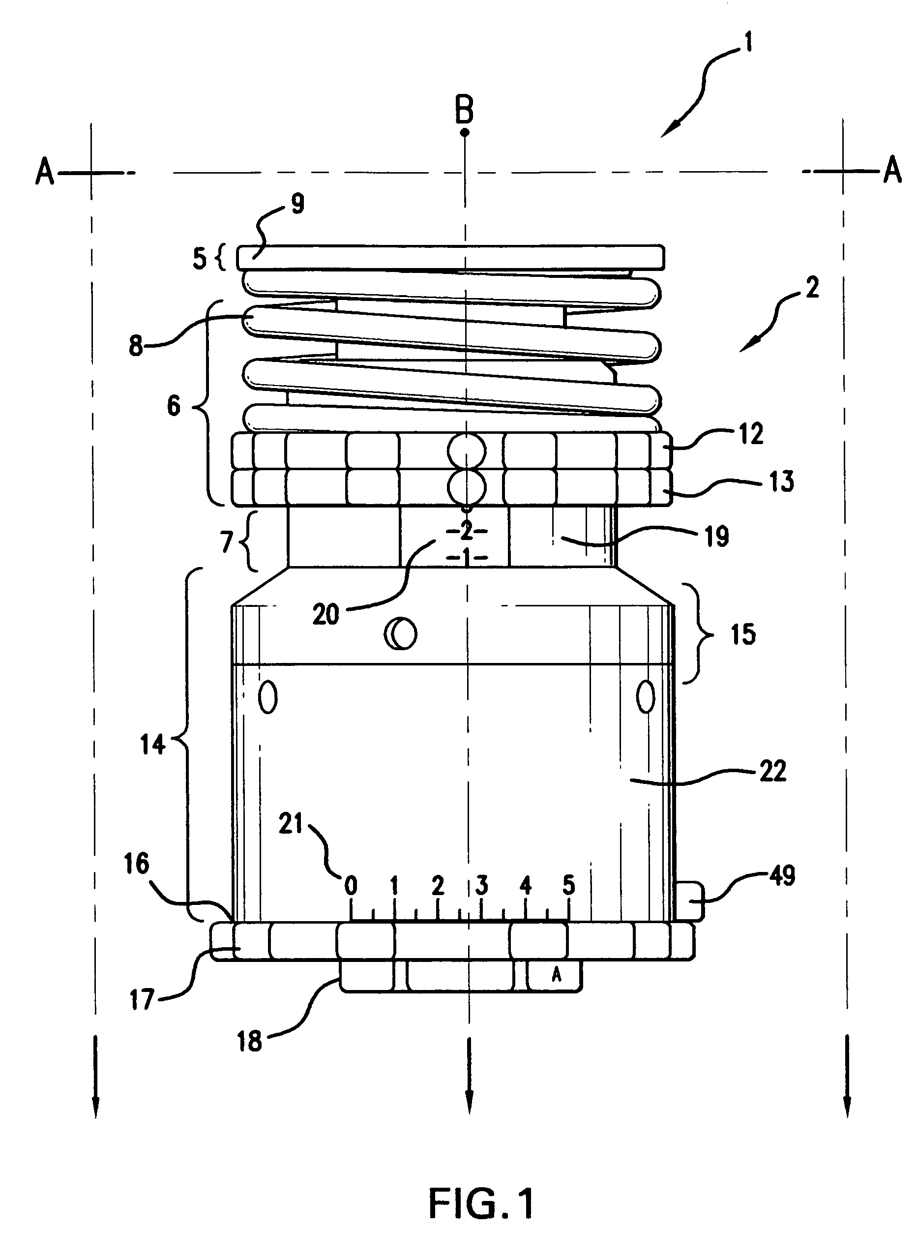
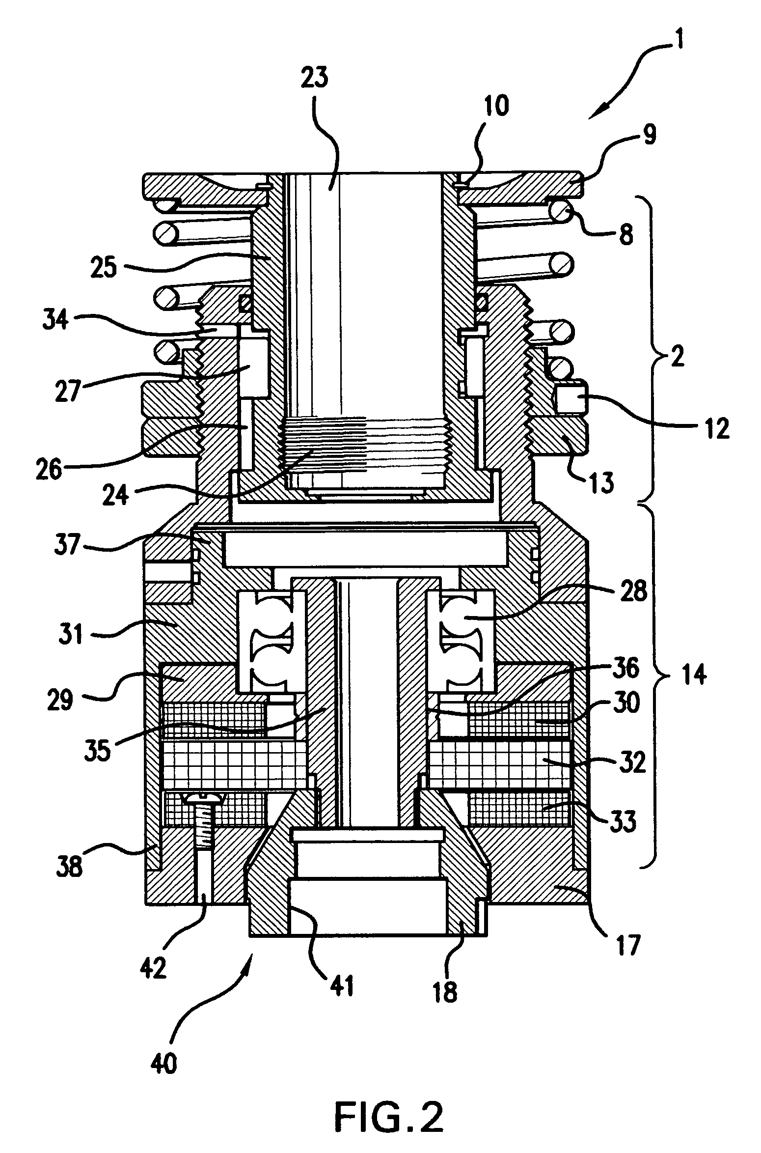
[0028]Thus, the invention disclosed and claimed herein deals with a capping head assembly for capping containers. Turning now to FIG. 1, there is shown a full side view of a device 1 of this invention. There is shown a first housing assembly 2 that is securable to a drive spindle, not shown. The first housing assembly 2 has a top portion 5, a middle portion 6, and a lower portion 7, and the first housing assembly 2 has a compression spring 8 surrounding it.

[0029]The compression spring 8 is mounted beneath a spring retention plate 9 and held in place around the first housing assembly 2 by the spring retention plate 9 and the spring retention plate 9 is held in place by a retainer ring 10 (shown in FIG. 2). The compression spring 8 slidably rests on a moveable spring pre-load adjustment ring 12 that is threadedly mounted around the middle portion of the first housing assembly 2 and said moveable spring pre-load adjustment ring 12 works in conjunction with a jam nut 13 to provide an ad...


PUM


Abstract

A device that is useful for applying pre-threaded closures onto threaded containers with improved sensitivity. The device allows for the adjustment of the torque that is required for capping containers such that variable sizes and variable types of containers can be capped.

Description

[0001]The invention claimed and disclosed herein deals with a device that is useful for applying pre-threaded closures onto threaded containers with improved sensitivity.BACKGROUND OF THE INVENTION[0002]It is known in the art to use capping devices for applying threaded caps to pre-threaded containers. Such devices utilize a clutch to control the amount of torque applied to the cap so that the container is properly closed but prevents too much torque from being applied that could strip the threads of the container and the cap. Also, it is desired to prevent the over tightening of the cap.[0003]This has been accomplished by using rings of concentric magnets with some form of control to control the axial position of the magnets. Various devices have also incorporated rings of magnets of alternating polarity. Even though such devices have been available, they have tended to be complex and costly, and not very reliable with regard to retaining the pre set torque, and thus many capping d...

Claims


Application Information

Patent Timeline
Patent Type & Authority Patents(United States)
IPC IPC(8): B67B3/20
CPCB67B3/2086
Inventor SCOTT, MICHAEL PATRICKDOTSON, LARRY DALE
Owner PRECISION TORQUE CONTROL
Why Eureka
Try Eureka