Conveying device for bulk material

a conveying device and bulk material technology, applied in the direction of conveying parts, conveyors, transportation and packaging, etc., can solve the problems of material sliding into the gap between the conveying fabric and the conveying belt, material scraping across the support parts, and slowed down material transportation, so as to reduce the risk of damage to the transport device and reduce the wear of the structural components of the conveying device.

Active Publication Date: 2007-02-27
GRIMME LANDMASCHINENFABRIK GMBH & CO KG
View PDF20 Cites 58 Cited by
  • Summary
  • Abstract
  • Description
  • Claims
  • Application Information

AI Technical Summary

Benefits of technology

[0006]It is an object of the present invention to provide a conveying device of the aforementioned kind in which a material deposit in the transition area from the conveying fabric to the conveying belt is prevented if possible, in which the transported goods are secured in a better way against undesirable loss by falling off, in which the material wear of the structural components of the conveying device is reduced, and in which the risk of damage being done by the transport device is also reduced.

Problems solved by technology

In the abutting area of the conveying fabric arranged between the conveying belts there is however the problem that material can slide into the gap between the conveying fabric and the conveying belts and can also be lost.
In this way, the gap is enlarged to a hole which leads to greater losses.
In such an arrangement, there is however the disadvantage that the material to be transported scrapes across the support parts and is therefore slowed down.
This leads to efficiency losses, and the transported material itself has the tendency to stay behind because of the braking effect and, in the case of a slanted conveying path, to roll down.
Moreover, sensitive material to be transported, for example, harvested material, can become damaged by the support parts by friction or by being jammed.
At the abutting locations between the support surfaces and the conveying belts or the support parts, gaps are generated through which gaps the transported goods can fall from the conveying member and can be lost.

Method used


Image

  • Conveying device for bulk material
  • Conveying device for bulk material
  • Conveying device for bulk material

Examples


Embodiment Construction

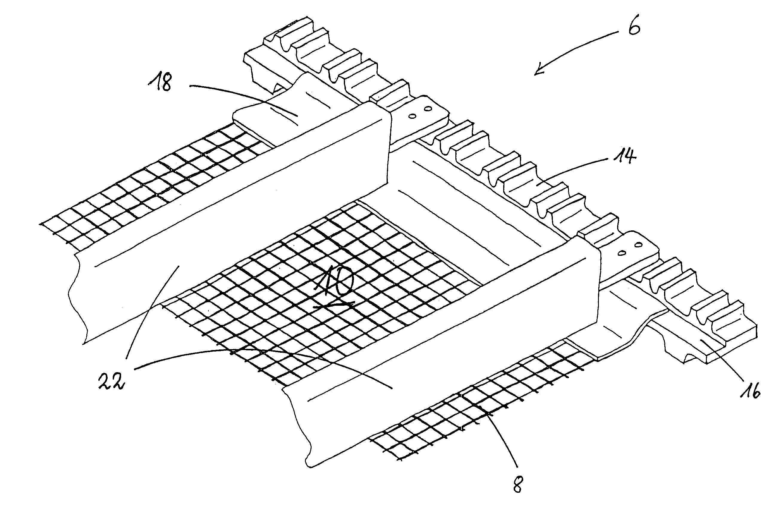
[0030]FIG. 1 shows a conveying device 2 having a support frame 4 on which an endless conveying member 6, illustrated only partially, is arranged so as to circulate. The conveying member 6 has support surfaces 10 that are separated from one another by partitioning elements 30. The conveying member 6 of the illustrated embodiment moves goods to be transported resting on the support surfaces 10 of a conveying fabric 8 in the conveying direction F. The goods to be transported resting on the support surfaces 10 are prevented by the partitioning elements 30 from rolling down the conveying member 6 counter to the conveying direction F. In order to prevent the material to be transported to drop or fall laterally off the support surfaces 10, support parts 12 are arranged at the sides of the support surfaces 10 of the conveying member 6. The support parts 12 can be attached either to the conveying member 6 or the support surfaces 10 of the conveying member 6; alternatively, the support parts ...


PUM


Abstract

A conveying device has a support frame and a conveying member with at least two driven conveying belts that circulate in parallel to one another and with a conveying fabric having at least one support surface and being arranged between the at least two conveying belts. The at least two conveying belts have inner sides facing one another; the inner sides have recesses. The conveying fabric has lateral edges inserted into the recesses. Support parts are attached in an overlapping area or an abutting area where the lateral edges of the conveying fabric and the at least two conveying belts overlap or abut one another. The support parts project upwardly past a plane of the support surface.

Description

BACKGROUND OF THE INVENTION[0001]The invention relates to a conveying device comprising a support frame, a conveying member that has at least two driven conveying belts that circulate in parallel to one another and a conveying fabric arranged between the conveying belts and having at least one support surface.[0002]Conveying devices for bulk material are known in a plurality of configurations. The bulk material to be transported by the conveying device is placed at point A onto the endless circulating conveying member and transported to point B where the bulk material or other transported goods are dispensed. In order for the goods that are being transported not to fall laterally off the conveying member, the known conveying devices are provided with support parts that project past the plane of the support surface of the conveying member and are designed to retain transported pieces that threaten to fall off the conveying member.[0003]European patent application 1 300 062 A1 disclos...

Claims


Application Information

Patent Timeline
Patent Type & Authority Patents(United States)
IPC IPC(8): B65G15/30B65G15/52B65G17/02B65G17/08B65G17/44
CPCB65G17/02B65G17/44B65G2812/02534
Inventor KALVERKAMP, KLEMENS
Owner GRIMME LANDMASCHINENFABRIK GMBH & CO KG
Why Eureka
Try Eureka