Method for Regulating The Pressure In An Electronically Controlled Brake System, and Electronic Brake System

a technology of electronic brake system and electronic brake, which is applied in the direction of brake system, brake components, vehicle components, etc., can solve the problems of noise generation, noise completely audible to the driver, and noise generation, so as to avoid noise generation and reduce the effect of material wear in the electronic brake system

Inactive Publication Date: 2009-05-07
CONTINENTAL TEVES AG & CO OHG
View PDF9 Cites 0 Cited by
  • Summary
  • Abstract
  • Description
  • Claims
  • Application Information

AI Technical Summary

Benefits of technology

[0025]An advantage of the invention is that through sensitive detection of movement it is possible to decide whether or not the motorcycle is moving, and consequently it is possible to make a decision as to whether or not an active pressure increase for assisting the driver is necessary.
[0026]A further advantage is avoiding the generation of noise by the electronic brake system. It is even possible that in stationary state situations the electronic brake system according to aspects of the invention will no longer be perceived. The material wear in the electronic brake system is likewise advantageously reduced according to aspects of the invention without having to accept a functional disadvantage as the cost.
[0027]These and other aspects of the invention are illustrated in detail by way of the embodiments and are described with respect to the embodiments in the following, making reference to the Figures.

Problems solved by technology

An active increase in brake pressure is always accompanied by a certain amount of noise and by wear.
For an active pressure increase, valves and a pump of the electronic brake system (EBS) are required and they generate a considerable amount of noise.
Particularly in the stationary state with the engine switched off or idling, the noise is completely audible to the driver and can be disruptive.

Method used


Image

  • Method for Regulating The Pressure In An Electronically Controlled Brake System, and Electronic Brake System
  • Method for Regulating The Pressure In An Electronically Controlled Brake System, and Electronic Brake System
  • Method for Regulating The Pressure In An Electronically Controlled Brake System, and Electronic Brake System

Examples


Embodiment Construction

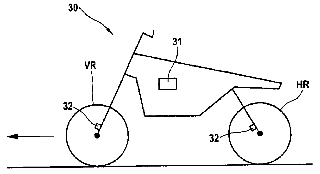
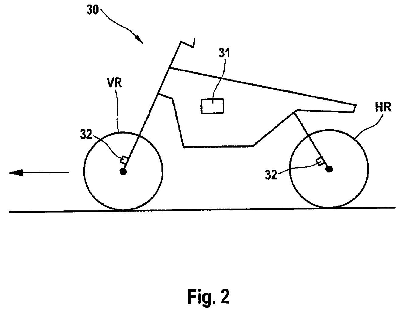
[0031]The method according to aspects of the invention is described below on the basis of a motorcycle brake system with partial integral braking function (see FIG. 1) but it can also be carried out in any other brake system in which an active increase in brake pressure is carried out when an activation event occurs. For example, the method can be carried out in a fully integral brake system of a motorcycle or in a passenger car brake system.

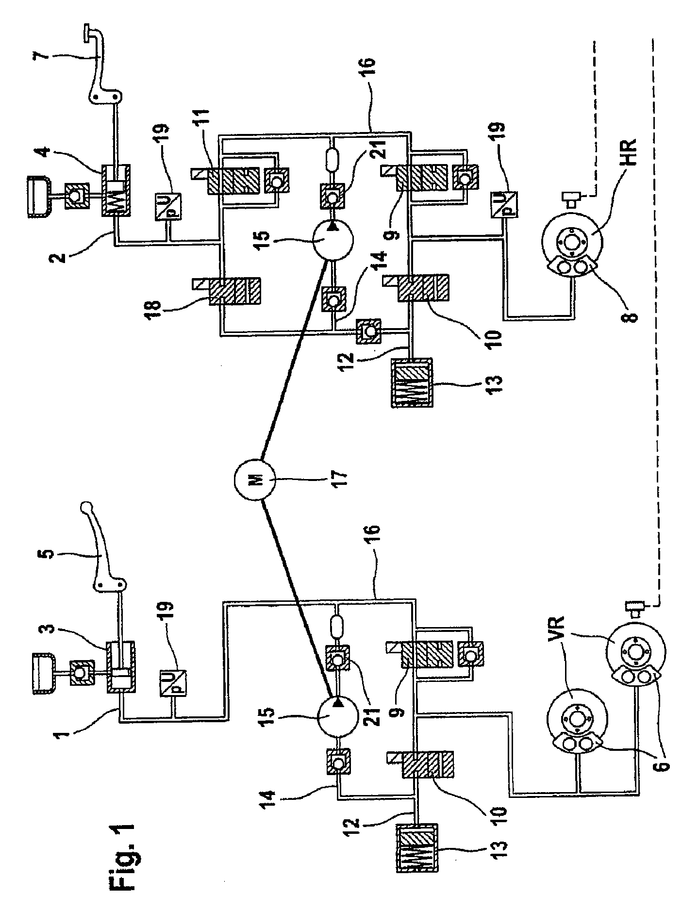
[0032]FIG. 1 is a schematic illustration of an exemplary partially integral brake system for a motorcycle. Said partially integral brake system is composed of two brake circuits 1, 2, one for the front wheel FW and one for the rear wheel RW, each with a master brake cylinder 3, 4. The driver directly activates the front wheel brake 6 with a handbrake lever 5, and the rear wheel brake 8 is activated with a foot pedal 7.

[0033]In order to regulate brake slip, inlet valve 9 and outlet valve 10 which can be activated electromagnetically are arranged ...


PUM


Abstract

A method for regulating the brake pressure in an electronically controlled brake system for a motor vehicle. According to the method, an activation event results in an active pressure increase in a brake circuit. The activation event may result in no active pressure increase in a brake circuit in certain situations in which the braking effect of the active pressure increase is not required. Also disclosed is an electronic brake system.

Description

CROSS-REFERENCE TO RELATED APPLICATIONS[0001]This application is the U.S. national phase application of PCT International Application No. PCT / EP2007 / 052817 filed Mar. 23, 2007, which claims priority to German Patent Application No. DE102006017357.0, filed Apr. 11, 2006, the contents of such applications being incorporated by reference herein in their entirety.BACKGROUND OF THE INVENTION[0002]1. Field of the Invention[0003]The invention relates to a method for regulating the pressure in an electronically controlled brake system, and electronic brake system.[0004]2. Description of the Related Art[0005]In the course of the last few decades, the motorcycle has developed from a cost-effective means of locomotion into a recreational vehicle in which emphasis is increasingly placed on the driver's safety and comfort.[0006]Similarly to motor vehicles several years ago, motorcycles are also being increasingly equipped with antilock brake systems (ABS). EP 0 548 985 B1 discloses, for example,...

Claims


Application Information

Patent Timeline
Patent Type & Authority Applications(United States)
IPC IPC(8): B60T8/17B60T8/32
CPCB60T8/1706B60T8/4072B60T8/3225B60T8/261
Inventor WOYWOD, JURGENMEIXNER, MICHAELZYSNO, RENE
Owner CONTINENTAL TEVES AG & CO OHG
Why Eureka
Try Eureka