Fluid dynamic bearing

a dynamic bearing and bearing bush technology, applied in the direction of sliding contact bearings, mechanical energy handling, mechanical equipment, etc., can solve the problems of affecting the bearing bush, and the bearing bush is prone to slipping, so as to reduce the wear

Active Publication Date: 2010-10-28
MINEBEAMITSUMI INC
View PDF8 Cites 0 Cited by
  • Summary
  • Abstract
  • Description
  • Claims
  • Application Information

AI Technical Summary

Benefits of technology

[0008]It is the object of the invention to provide a fluid dynamic bearing in which the effects of the above-mentioned problem of

Problems solved by technology

In this known embodiment of a fluid dynamic bearing, the problem that arises particularly when the bearing starts and stops is that the moving bearing component, mostly the shaft, tilts in the bearing bore of the stationary bearing component.
When the relative speed between the bearing components is low or when they are at a standstill, the bearing groove patterns do not produce sufficient fluid dynamic pressure in the bearing, so that the shaft within the bearing bore becomes accordingly tilted.
Particularly in the transition region between the bearing groove patterns a

Method used


Image

  • Fluid dynamic bearing
  • Fluid dynamic bearing
  • Fluid dynamic bearing

Examples


Embodiment Construction

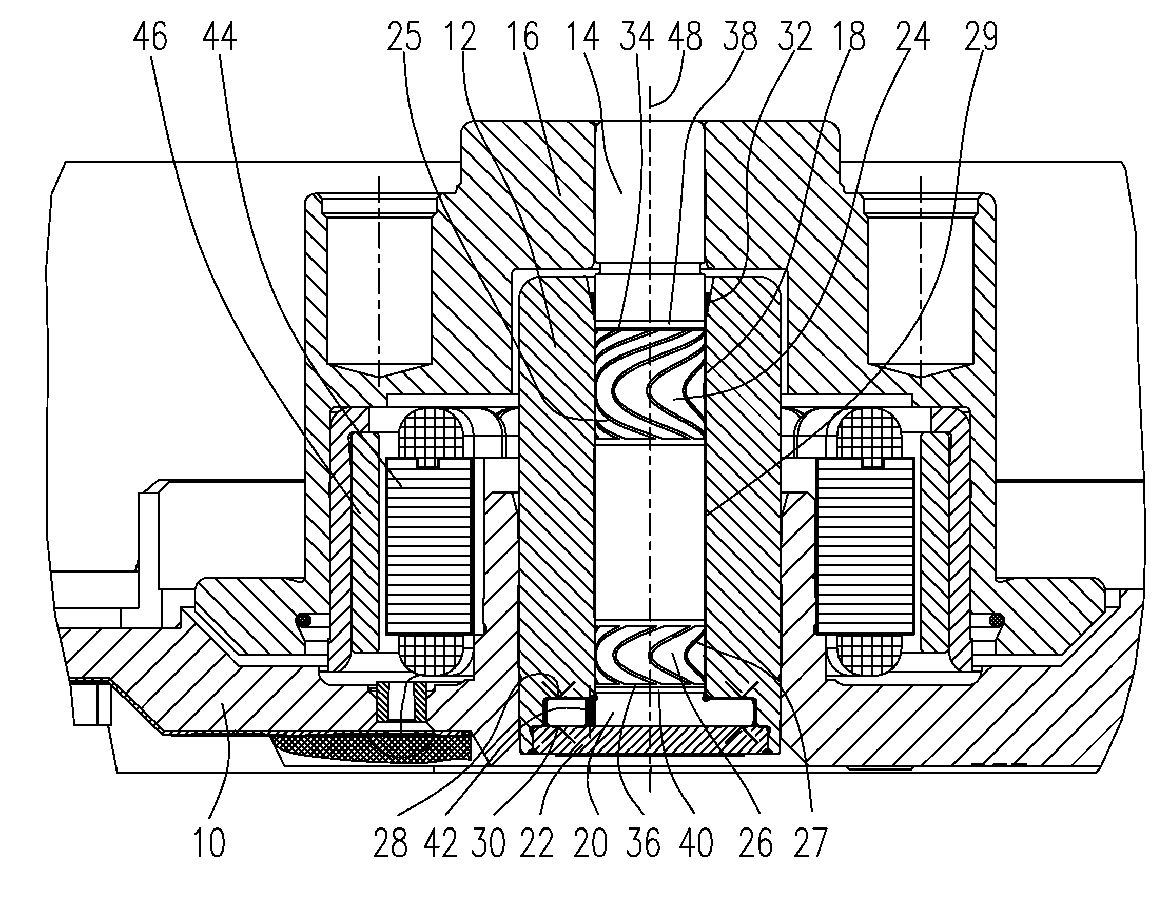
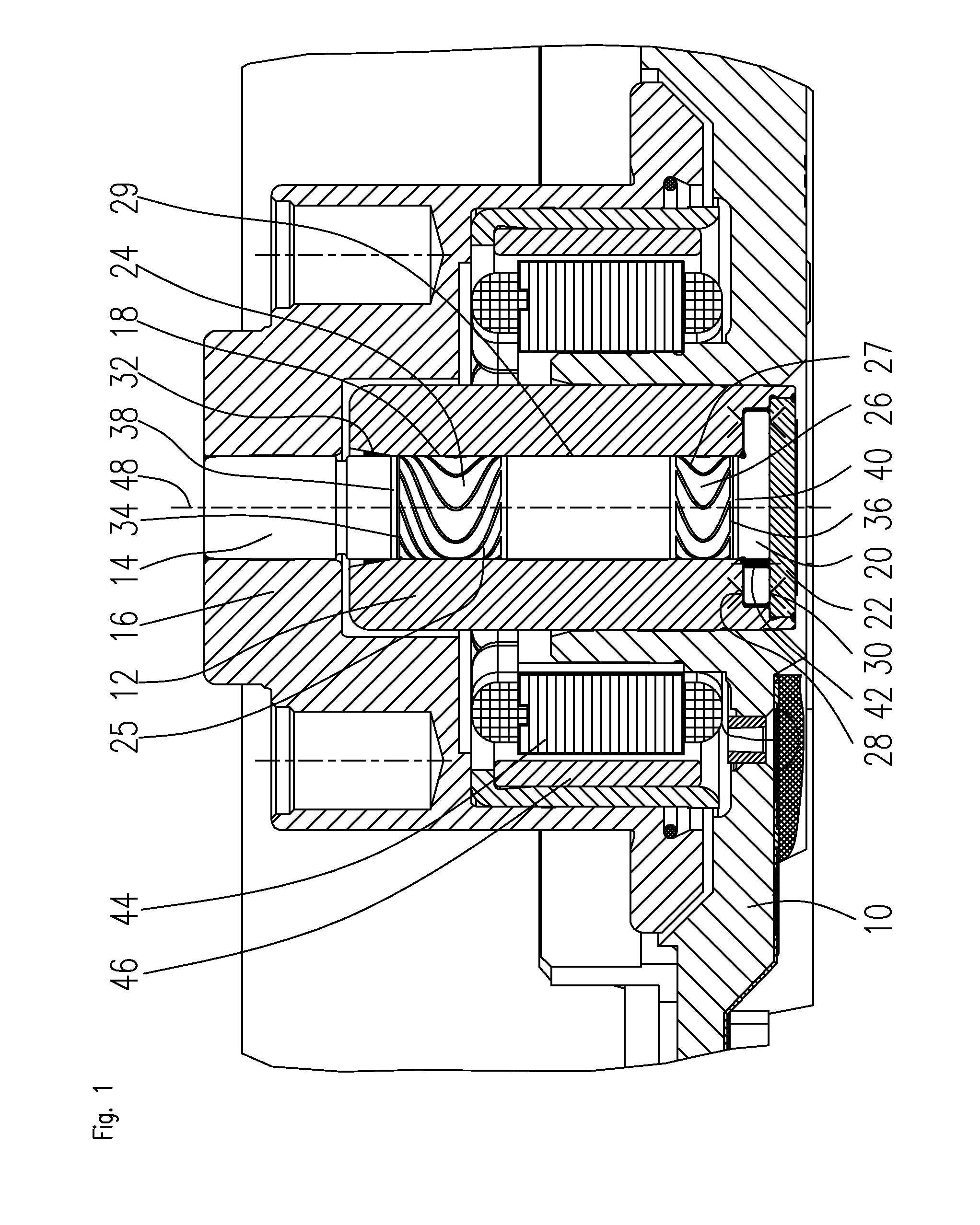
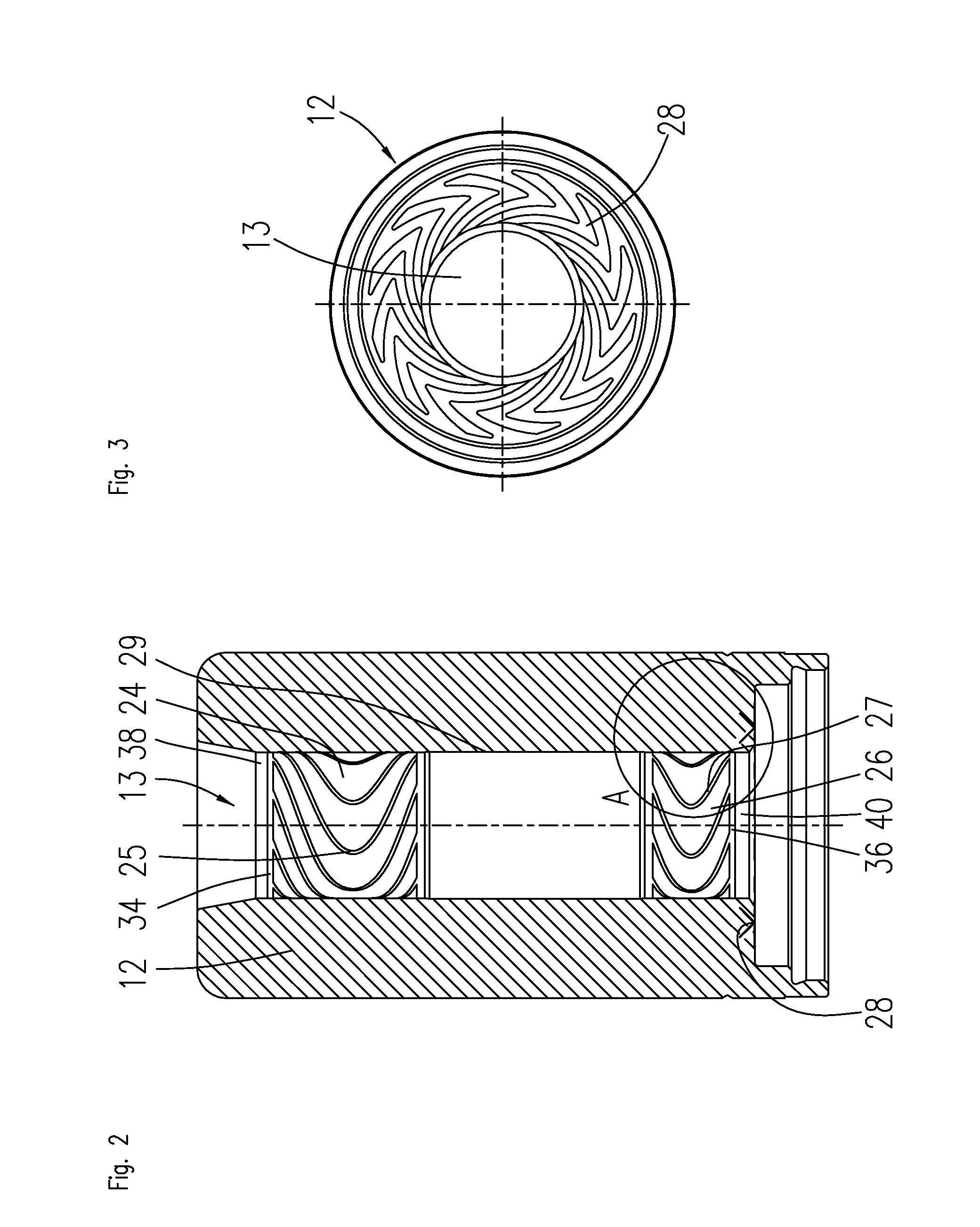
[0033]FIG. 1 shows a section through a spindle motor that is rotatably supported using a bearing according to the invention. The spindle motor comprises a stationary baseplate 10 in which a bearing bush 12 is fixed. The bearing bush 12 has an axial cylindrical bearing bore 13 in which a shaft 14 is rotatably accommodated. The bearing bush 12 and the shaft 14 together form a part of the fluid dynamic bearing system. A bearing gap 18 filled with a bearing fluid, such as a lubricating oil, is provided between the inside diameter of the bearing bore 13 and the somewhat smaller outside diameter of the shaft 14. The bearing gap preferably has a gap width of a few micrometers. The fluid dynamic bearing system comprises two radial bearing regions 24, 26 that are marked by corresponding radial bearing grooves 25, 27. The radial bearing grooves 25, 27 are provided on the surface of the bearing bore 13 and / or the surface of the shaft 14. The two radial bearing regions 24, 26 are separated axia...


PUM


Abstract

The invention relates to a fluid dynamic bearing system having a stationary bearing component and a moving bearing component, that are separated from one another by a bearing gap filled with a bearing fluid. There are two radial bearing regions separated from one another and marked by radial bearing grooves. A separator region having a larger bearing gap width is disposed between the radial bearing regions. The radial bearing grooves of the two radial bearing regions have inner ends facing each other and outer ends facing away from each other. At least the outer ends of the radial bearing grooves are connected to each other by connecting grooves. According to the invention, wear zones provided especially for this purpose are disposed adjoining the connecting grooves, so as to prevent material wear at other regions of the bearing.

Description

BACKGROUND OF THE INVENTION[0001]The invention relates to a fluid dynamic bearing used particularly for the rotatable support of a spindle motor. These kinds of spindle motors are used, for example, for driving hard disk drives or fans.PRIOR ART[0002]Fluid dynamic bearing systems of a well-known design comprise a stationary bearing component and a moving bearing component that are separated from one another by a bearing gap filled with a bearing fluid. Two radial bearing regions that are separated from one another and marked by radial bearing grooves are usually provided. The radial bearing grooves of the two radial bearing regions have inner ends facing each other and outer ends facing away from one another. The outer ends of the radial bearing grooves may be connected to each other by connecting grooves.[0003]U.S. Pat. No. 5,407,281 A shows a fluid dynamic bearing having radial bearing grooves whose ends are connected to each other by connecting grooves. The connecting grooves are...

Claims


Application Information

Patent Timeline
IPC IPC(8): H02K7/08F16C32/06
CPCF16C17/246F16C2240/46F16C33/107F16C17/107
Inventor WINTERHALTER, OLAF
Owner MINEBEAMITSUMI INC
Why Eureka
Try Eureka