Electronic flare

a technology of electric flares and flares, which is applied in the field of emergency flares, can solve the problems of inconvenient use, inconvenient storage of phosphorus flares aboard a vessel, and inability to achieve high-intensity light transmission, etc., and achieves the effects of reducing the use of pyrotechnic flares, safe for users, and effective

Inactive Publication Date: 2007-02-27
ACR ELECTRONICS INC
View PDF7 Cites 26 Cited by
  • Summary
  • Abstract
  • Description
  • Claims
  • Application Information

AI Technical Summary

Benefits of technology

[0007]The light intensity generated by the present invention is greater than 500 candela. The light is generated by the output from a pulsating xenon strobe flash tube encased partially in a light reflective internal housing having a radiating solid angle of less than 6 steradians. Limiting the direction of light provides a safe optical solution for the user to prevent eye damage while increasing the pulsating strobe light beam intensity and range.
[0014]It is another object of this invention to provide a safe signal flare that eliminates the use of pyrotechnic flares especially in marine environment.
[0015]And yet still another object of this invention is to provide a very high-intensity portable light beam that is safe for the user and effective for search and rescue, especially in a marine environment.

Problems solved by technology

The great drawback to phosphorus flares is their inherent hazardous nature because of the burning material.
Storage of such flares aboard a vessel is always dangerous because of the possibility of accidental ignition, especially in the presence of other hazardous materials aboard ship such as gasoline and fuel oil.
The difficulty in replacing the conventional flare is to find a viable replacement that can provide sufficient light intensity for emergency situations.
This device is not capable of high-intensity light transmission and would not be suitable as an emergency electric flare.
The main problem with this device is that it does not produce a very high strobe light intensity required to compare illumination intensity between a pyrotechnic flare and the strobe light shown in this patent.
There is no safety feature to hide high-intensity light from the eyes of a user since the light transmits 360 degrees.
Also there are no optical features that could amplify and intensify the amount of light energy concentrated in a specific area.
None of the prior art references show a comparable electronic or electrically activated light source of high-intensity that can sustain the intensity of a pyrotechnic flare.
Hand-held phosphorus flares are inherently dangerous once ignited because of the high torching temperatures even though phosphorus has a tremendous ability for generating an intense light source that enables search and rescue parties to find people in distress, especially in emergency situations at sea.

Method used


Image

  • Electronic flare
  • Electronic flare
  • Electronic flare

Examples


Embodiment Construction

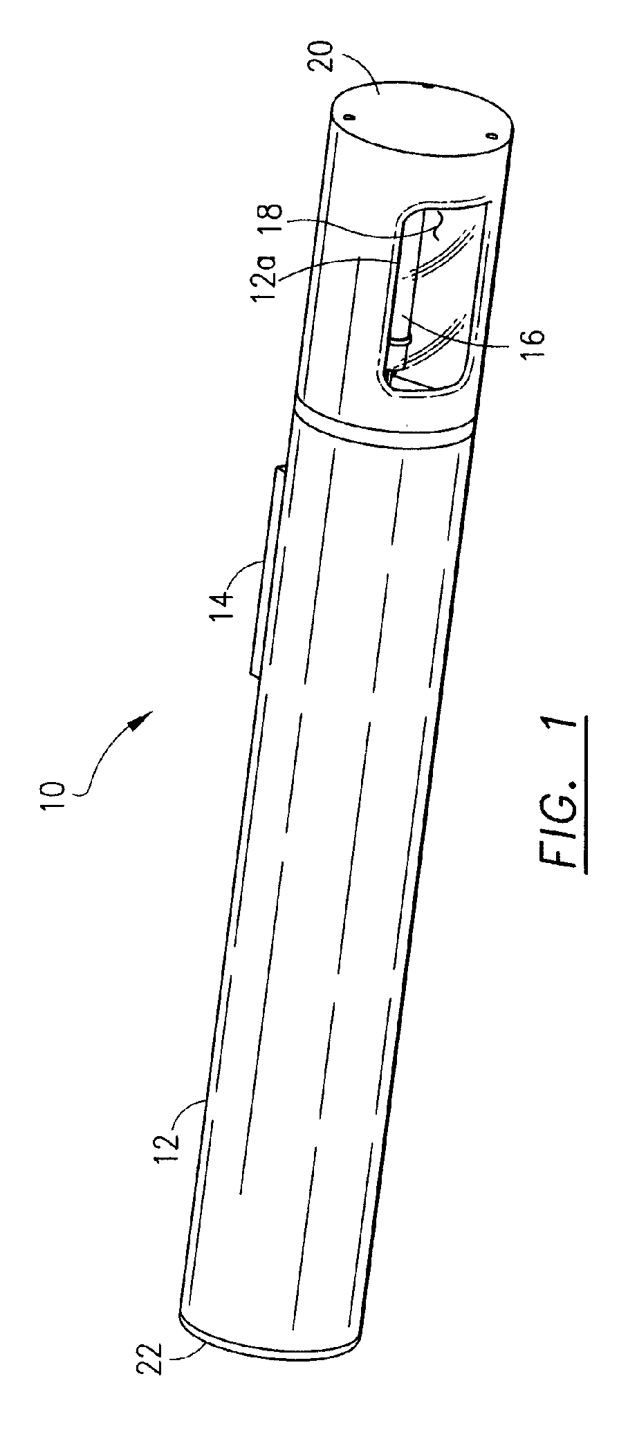
[0030]Referring now the drawings and, in particular, FIG. 1, one embodiment of the present invention is shown generally at 10 comprised of a tubular housing 12 having sealed end caps 20 and 22. The housing 12 is a tubular rigid structure constructed of plastic or metal. The electronic flare 10 includes an exterior magnetic switch 14 to turn the strobe light flash tube 16 to the “on” position illuminating the light. The housing 12 has an aperture 12a covered by a clear plastic 18 in the upper portion that provides for a directed beam of light that eminates from inside the tubular housing 12 less than 6 steradians of solid angle.

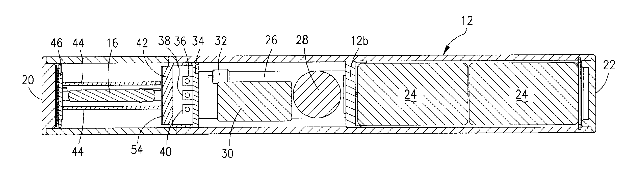
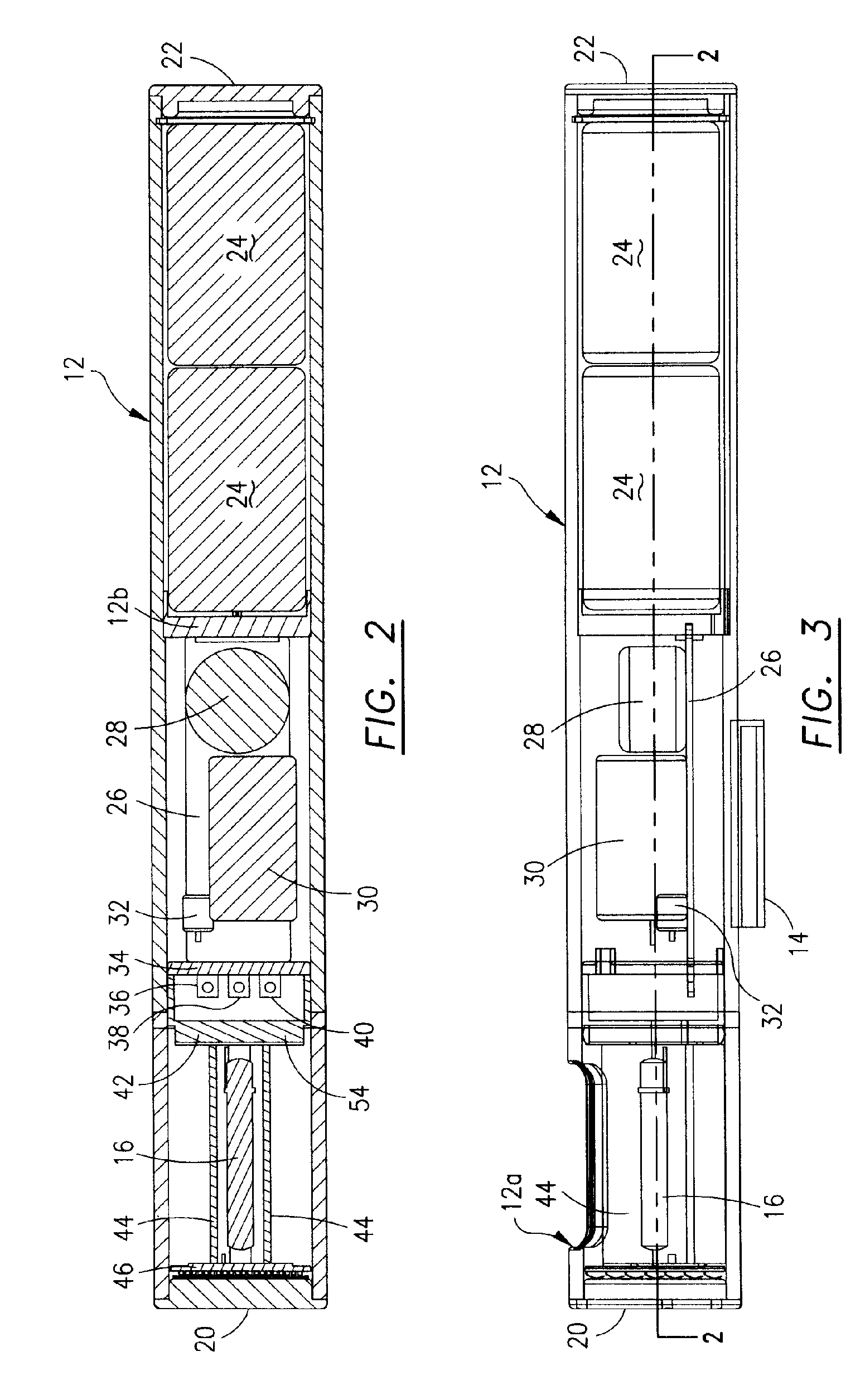
[0031]Referring now to FIGS. 2 and 3, the outer housing 12 is shown as a tubular housing divided into three different sections by panel 12b and panel 34 which is discussed below. Two batteries 24 are mounted in series in the battery section which is separated from the rest of the device by partition 12b which may be an electrical insulative separation. The bat...


PUM


Abstract

A portable, hand-held, electrically powered, high intensity directed light beam generating device for use as a replacement for a pyrotechnic flare for search and rescue, especially in a marine environment. The light intensity is generated by a xenon strobe flash tube in a covered, mirror reflective housing that allows for a directional beam of light of less than 6 steradians. The limited radiation light direction provides a safe optical solution for the user to prevent eye damage while increasing the beam intensity and range. The light and illumination section surrounding the strobe flash tube includes thermally conductive paths for the heat generated by the flash tube to be transmitted to the outside of the housing.

Description

FIELD OF THE INVENTION[0001]This invention relates generally to an emergency flare for use in search and rescue, especially in a marine environment, and particularly to an electric flare that can replace a conventional pyrotechnic flare.DESCRIPTION OF RELATED ART[0002]The use of hand-held flares made from pyrotechnic material such as a phosphorus burnable material is quite well known. In fact such conventional flares are required on marine vessels in the United States by the U.S. Coast Guard. The great drawback to phosphorus flares is their inherent hazardous nature because of the burning material. Storage of such flares aboard a vessel is always dangerous because of the possibility of accidental ignition, especially in the presence of other hazardous materials aboard ship such as gasoline and fuel oil.[0003]The difficulty in replacing the conventional flare is to find a viable replacement that can provide sufficient light intensity for emergency situations. U.S. Pat. No. 6,549,121 ...

Claims


Application Information

Patent Timeline
Patent Type & Authority Patents(United States)
IPC IPC(8): F21V15/04
CPCF21L4/00F21V7/005F21V7/0075F21V23/02F21Y2113/02F21W2111/10F21Y2101/02F21Y2103/00F21Y2113/20F21Y2115/10
Inventor FLOOD, JOHN F.SUBRATTEE, LESTER A.
Owner ACR ELECTRONICS INC
Why Eureka
Try Eureka