Eye tracking architecture

Inactive Publication Date: 2021-02-11
INTERFACE TECH CHENGDU CO LTD +2
View PDF0 Cites 0 Cited by
  • Summary
  • Abstract
  • Description
  • Claims
  • Application Information

AI Technical Summary

Benefits of technology

The present invention provides an eye tracking system that uses a hot mirror design to reflect infrared light and prevent damage to the user's eye. The system calculates the position and tracks the user's eye by analyzing the pupil and infrared pattern on the hot mirror. The hot mirror design prevents the need for active infrared beam projection, ultimately improving the accuracy of the eye tracking system while avoiding damage to the eyeball.

Problems solved by technology

It can be seen that there are disadvantages in the prior art that need to be improved.

Method used


Image

  • Eye tracking architecture
  • Eye tracking architecture
  • Eye tracking architecture

Examples


Embodiment Construction

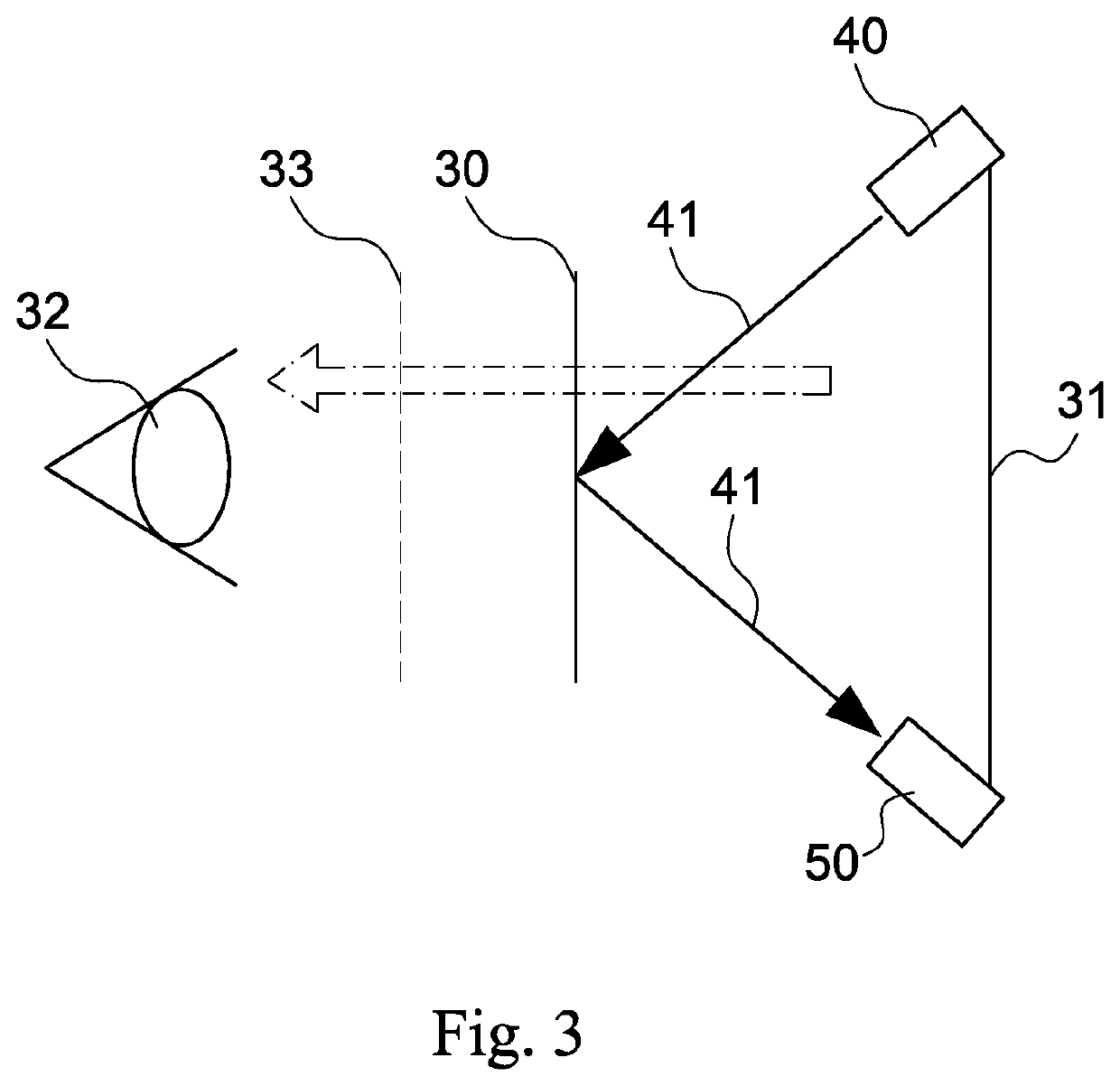
[0027]Refer to FIGS. 3, 4, and 5. The eye tracking architecture of the present invention comprises a hot mirror 30, an infrared light source 40, and a camera 50.

[0028]The hot mirror 30 is disposed in a head mounted display device between a display 31 and a user's eye 32.

[0029]The infrared light source 40 is provided to the headset display 31. A control circuit (not shown) controls the infrared light source 40 and an analyzer for measuring the movement locus of the infrared pattern on the hot mirror 30. The hot mirror 30 reflects infrared light 41 and an infrared pattern 42 is formed on the hot mirror 30.

[0030]The camera 50 is provided in the head mounted device display 31 and electrically connected to the control circuit. The camera captures images of the infrared pattern 42 on the heat mirror 30, captures images of the human eye 32, and captures composite images 52 of the eye 32 and infrared pattern 42 and transmits the image data to the control circuit.

[0031]The control circuit pe...


PUM


Abstract

An eyeball tracking architecture comprises a hot mirror, an infrared light source, and a camera. The hot mirror is disposed between a display in a head mounted display device and a human eye. The camera is disposed in the head mounted display and connected to a control circuit. The camera captures images of the infrared pattern reflected by the hot mirror, captures images of the human eye, and captures composite images of the infrared pattern and the eye and sends the image data to the control circuit. The control circuit performs compensation calculations using a line of sight mapping function, and calculates a position where the line of sight falls on the display. Then, the control circuit controls the display to display data relevant to and according to the image data and eye position.

Description

CROSS-REFERENCE TO RELATED APPLICATIONS[0001]This non-provisional application claims priority under 35 U.S.C. § 119(a) on Patent Application No(s). 201910737436.1 filed in China on Aug. 9, 2019, the entire contents of which are hereby incorporated by reference.BACKGROUND OF THE INVENTIONField of the Invention[0002]The present invention relates to eye tracking devices, and more particularly to an eye tracking architecture that utilizes a hot mirror to reflect infrared light and then determines eye position and tracking by comparing the user's pupil with the infrared pattern on the hot mirror.Description of the Prior Art[0003]Eyeball tracking technology originated in medical research and development. With advancements in technology it has been applied in commercial applications and has been used in a variety of devices such as mobile phones, computers, and automobiles.[0004]Eye tracking was derived from gaze point rendering technology. With improvements in the development of the augme...

Claims


Application Information

Patent Timeline
IPC IPC(8): G06F3/01H04N5/33
CPCG06F3/013H04N5/332G02B27/0093G02B27/0101G02B27/48H04N5/33G02B27/0172G02B2027/0187H04N23/11
Inventor LIN, PO-CHING
Owner INTERFACE TECH CHENGDU CO LTD
Why Eureka
Try Eureka