
Photoplethysmographic device for measuring a heart rhythm

Active Publication Date: 2017-05-11
LIVASSURED BV
View PDF1 Cites 5 Cited by
  • Summary
  • Abstract
  • Description
  • Claims
  • Application Information

AI Technical Summary

Benefits of technology

The invention aims to create a device that can measure heart rhythm when a subject's skin is pressed by a photoplethysmographic sensor while still providing comfort for the subject wearing the device.

Problems solved by technology

There is however for the wearer no easy way to know if the PPG signal has the highest amplitude when the sensor is attached on the skin.
Usually wearer instructions are vague and wearers tend to wear the sensor more tightly than is required.
This may lead among other things to skin irritation.
Such strategies however can be time consuming and bulky, whereas a wearer may want a measurement on short notice.
When the fastening band is loose (e.g. as a wearer would normally wear a watch) there is a bad contact pressure and no PPG signal can be measured.
If the fastening band or bracelet is too tight this will lead to pain because the skin is compressed.
In addition, a too tight fastening band will have a detrimental effect on the PPG signal since the compressed capillaries will decrease the blood circulation.

Method used


Image

  • Photoplethysmographic device for measuring a heart rhythm
  • Photoplethysmographic device for measuring a heart rhythm
  • Photoplethysmographic device for measuring a heart rhythm

Examples


Embodiment Construction

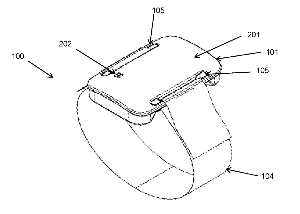
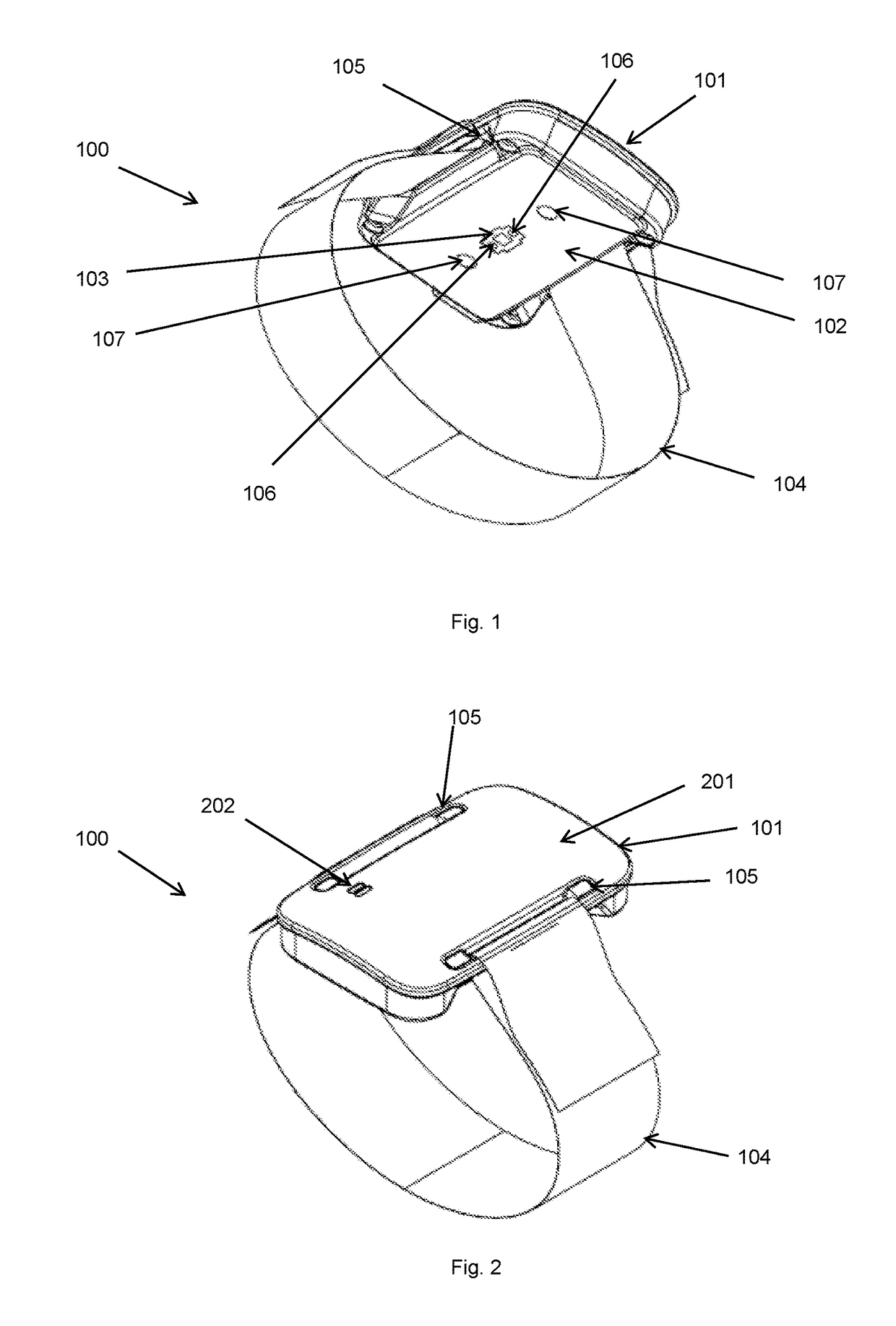
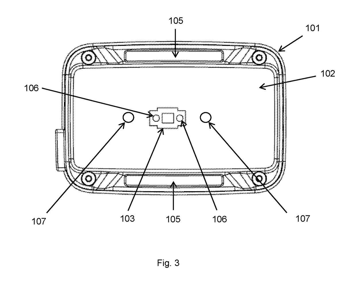
[0024]FIG. 1 shows a perspective bottom view of the photoplethysmographic device 100 having a housing 101 and a strap or wristband 104. The housing 101 has a contacting surface 102 at the bottom side of the housing 101, which is to be brought into contact with a subject's skin. The contacting surface has a photoplethysmographic (PPG) sensor 103, comprising a photodetector and Light Emitting Diodes 106 (LEDS) positioned laterally of the photodetector. The device 100 can for example be applied to the subject's wrist, however other body parts, i.e limbs and parts thereof may also apply. The strap or wristband 104 can for example be connected to the housing 101 by pulling the strap or wristband end through recesses 105 of the housing. This way a user or wearer can manually tighten the device 100 as much as is required. On the contacting surface 102 one or more pressure sensors 107 can be provided. The pressure sensors 107 can be of the resistive type, such as Flexiforce™ sensors, which ...


PUM


Abstract

Photoplethysmographic device for measuring a heart rhythm, comprising a housing having a contacting surface and a control unit, a photoplethysmographic sensor mechanically attached to the contacting surface and connected to the control unit, wherein the control unit is arranged to receive a photoplethysmographic signal from the photoplethysmographic sensor, a fastening band having a first end and a second end, the first end and second end attached to the device for attaching the device to a subject with the contacting surface contacting the subject's skin, a pressure sensor attached to the contacting surface in close proximity to the photoplethysmographic sensor. The control unit is arranged determining whether the pressure from the pressure sensor is in a range suitable for photoplethysmographic measurement by the photoplethysmographic sensor.

Description

FIELD OF THE INVENTION[0001]The invention relates to a photoplethysmograpicy device for measuring a heart rhythm.BACKGROUND OF THE INVENTION[0002]Photoplethysmographic (PPG) measuring of heart rhythm uses a light source such as a Light Emitting Diode (LED) which irradiates light into a subject's skin. Light reflected from deeper layers in the skin is detected by a photodetector. Alternatively, light transmitted through the skin and tissue may be measured. As the blood flow through the skin varies with every heartbeat, so does the reflection or transmission of the light in or through the skin vary. The variation is detected by a control circuit and a heart rhythm may be determined from this variation.[0003]PPG sensors can be integrated in wearables such as cuffs arranged for heart rhythm measurement, wristbands of smartwatches and the like.[0004]The amplitude of a PPG signal from such PPG sensor in reflection and transmission mode depends on the pressure exerted by the sensor and the...

Claims


Application Information

Patent Timeline
IPC IPC(8): A61B5/024A61B5/00
CPCA61B5/02416A61B5/02438A61B5/6831A61B5/746A61B5/0002A61B5/681A61B5/6843
Inventor UNGUREANU, CONSTANTINTIELENS, THEO ARY ASMUND
Owner LIVASSURED BV
Learn More