Coolant delivery apparatus for machine tool

a technology for machine tools and cooling equipment, which is applied in the field of machine tools, can solve the problems of requiring a larger volume of coolant, interfering with machine components,

Active Publication Date: 2007-02-27
GLEASON WORKS
View PDF14 Cites 15 Cited by
  • Summary
  • Abstract
  • Description
  • Claims
  • Application Information

AI Technical Summary

Problems solved by technology

Having many coolant lines, and hence many coolant nozzles, can result on interference situations with machine components as well as requiring a greater volume of coolant as the number of lines increases.

Method used


Image

  • Coolant delivery apparatus for machine tool
  • Coolant delivery apparatus for machine tool
  • Coolant delivery apparatus for machine tool

Examples


Embodiment Construction

[0016]In the drawings, which illustrate the present invention by way of example only, like components will be identified with the same reference number.

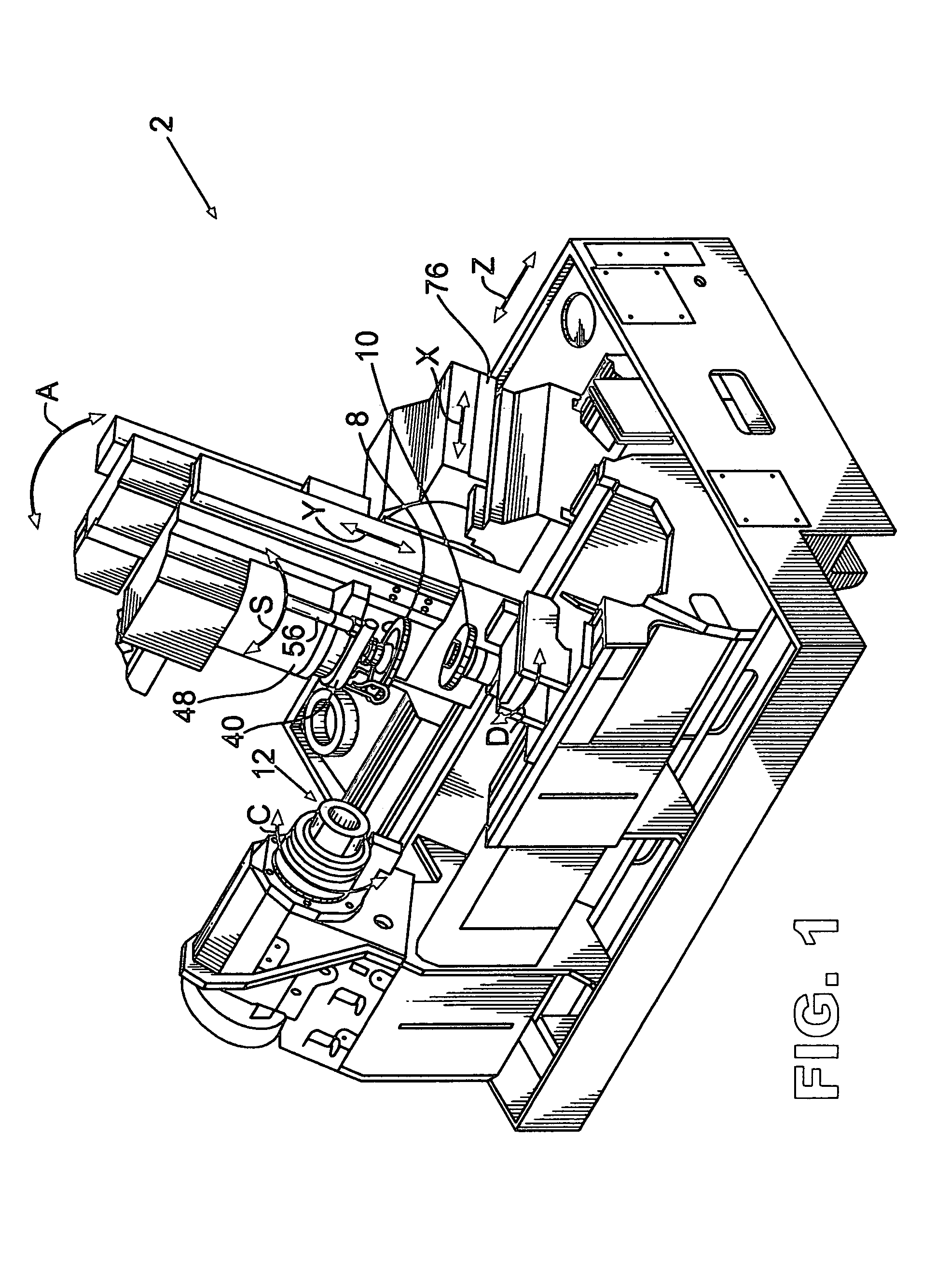
[0017]FIG. 1 illustrates one type of cutting blade grinding machine 2. The machine is shown only with those elements necessary to gain a general understanding of the machine since the machine, per se, is not part of the present invention. Machines of this type are commercially available, for example, from The Gleason Works, Rochester, N.Y.

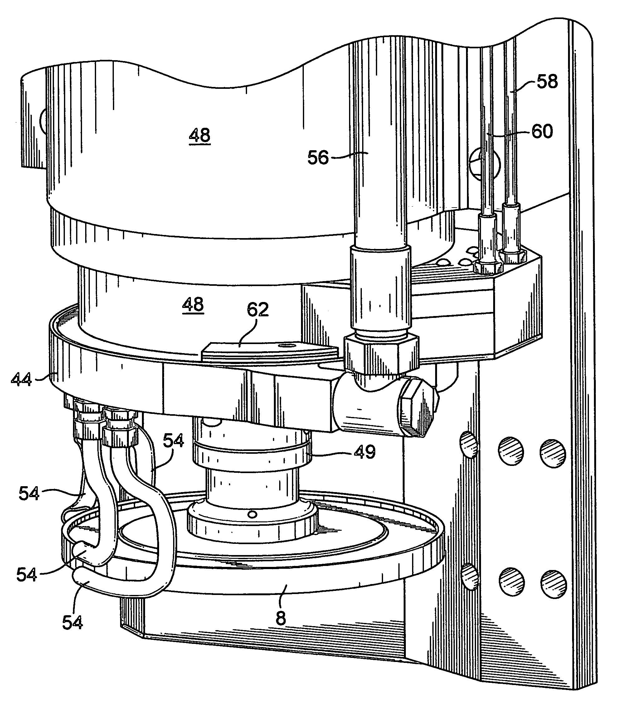
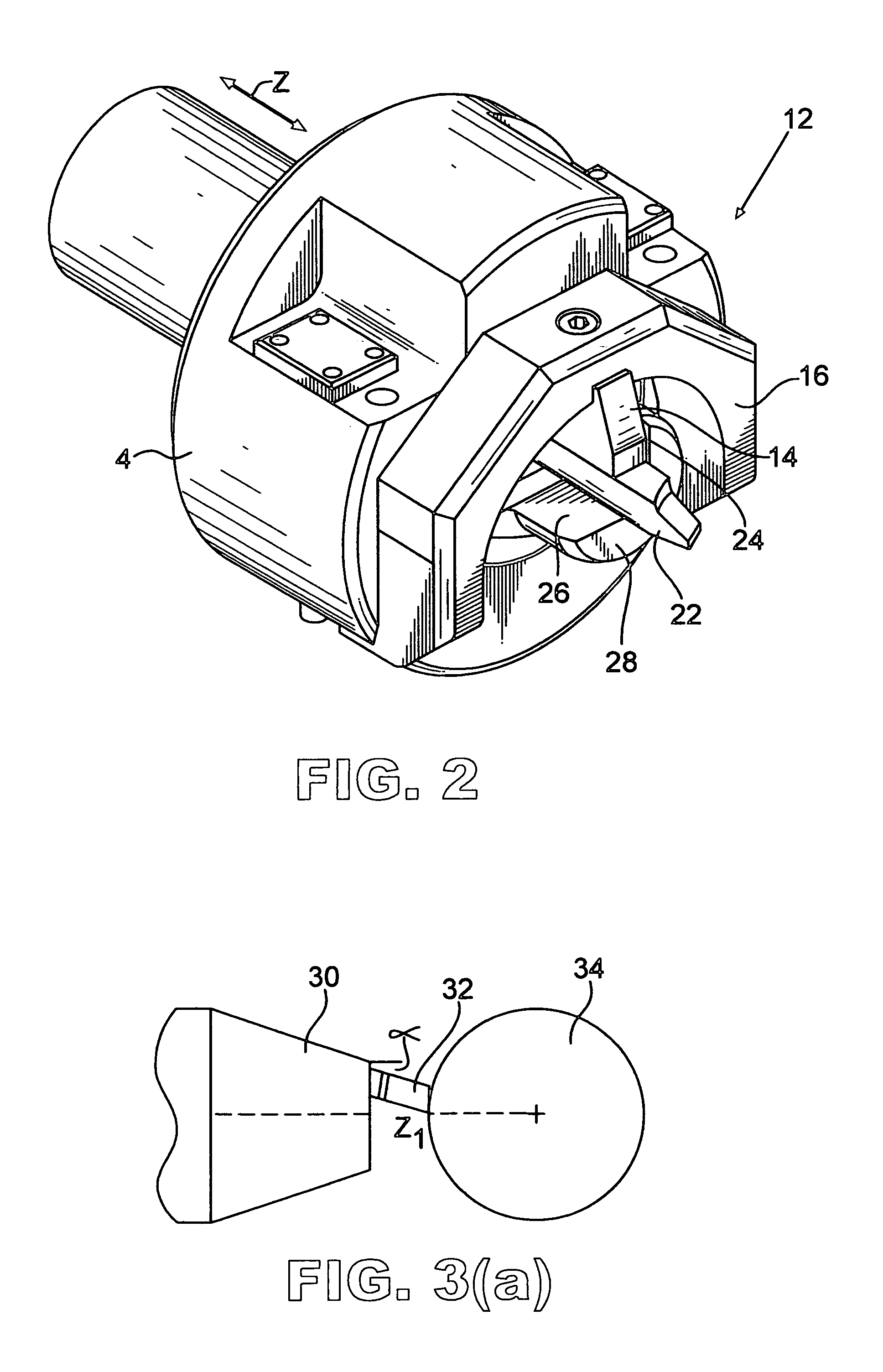
[0018]In FIG. 1, grinding machine 2 includes a workpiece clamping mechanism 12 rotatable in a direction C about the axis of the clamping mechanism and a grinding wheel 6 rotatable in a direction S about the axis of the grinding wheel. The grinding wheel is movable relative to the clamping mechanism in three linear directions X, Y and Z (preferably mutually perpendicular) and is angularly positionable in a direction A. The grinding machine includes a dressing mechanism 10, rotatable in a direction D,...


PUM

PropertyMeasurementUnit
areaaaaaaaaaaa
movementaaaaaaaaaa
top angleaaaaaaaaaa

Abstract

A coolant delivery apparatus for a machine tool wherein the position of the coolant delivery apparatus is controllable such that coolant may be delivered to the machining contact zone of a tool even though the location of the machining zone of the tool may change such as during machining of a workpiece, or from one workpiece to another.

Description

[0001]This application claims the benefit of U.S. Provisional Patent Application No. 60 / 459,122 filed Mar. 31, 2003.FIELD OF THE INVENTION[0002]The present invention is directed to machine tools and in particular to an apparatus for delivering coolant to a tool and workpiece during machining, especially during grinding of cutting blades.BACKGROUND OF THE INVENTION[0003]It is well known to manufacture gears, such as bevel and hypoid gears, with stick-type cutting blades made from, for example, high speed steel or carbide materials. It is further known that to form, or to restore, the desired surfaces and edges on stick-type cutting blades, grinding operations must be performed on the cutting blades. Examples of such cutting blades can be found in U.S. Pat. No. 4,575,285 to Blakesley; U.S. Pat. No. 5,890,846 to Clark et al. or U.S. Pat. No. 6,120,217 to Stadifeld et al. Cutting blades of this type have cutting and clearance profile surfaces as well as a top surface that are ground dur...

Claims


Application Information

Patent Timeline
Patent Type & Authority Patents(United States)
IPC IPC(8): B24B1/00B24B55/02B23Q11/10B24B3/34
CPCB23Q11/10B24B55/02B24B3/346B23Q11/1076
Inventor MUNDT, ERIC G.
Owner GLEASON WORKS
Why Eureka
Try Eureka