Delayed video tracking

a video tracking and delay technology, applied in the field of tracking systems, can solve problems such as delay, image compression/decompression, link bandwidth limitations,

Inactive Publication Date: 2007-02-27
RAFAEL ADVANCED DEFENSE SYSTEMS
View PDF7 Cites 33 Cited by
  • Summary
  • Abstract
  • Description
  • Claims
  • Application Information

AI Technical Summary

Problems solved by technology

Generally, the main factors contributing to the delay are signal processing, image compression / decompression, and / or link bandwidth limitations.
Clearly, this time delay complicates the efforts to lock remote tracker 30 onto the object.
As such, the effect is a continuous feedback control loop with delay, a situation which is liable to suffer from overshoots and instability.
The locking process is complicated even more by the human input in the tracking loop.
Humans do not function well in feedback loops with time delay, such an example being the typical daily experience of adjusting the temperature of hot water from a faucet with a slow reaction time.

Method used


Image

  • Delayed video tracking
  • Delayed video tracking
  • Delayed video tracking

Examples


Embodiment Construction

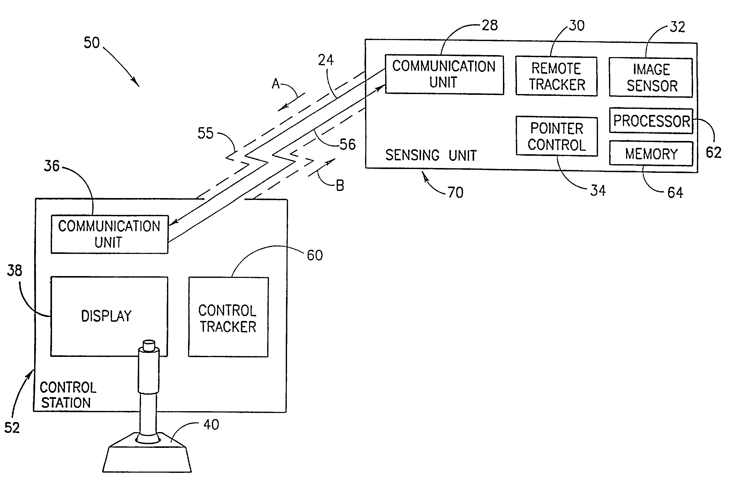
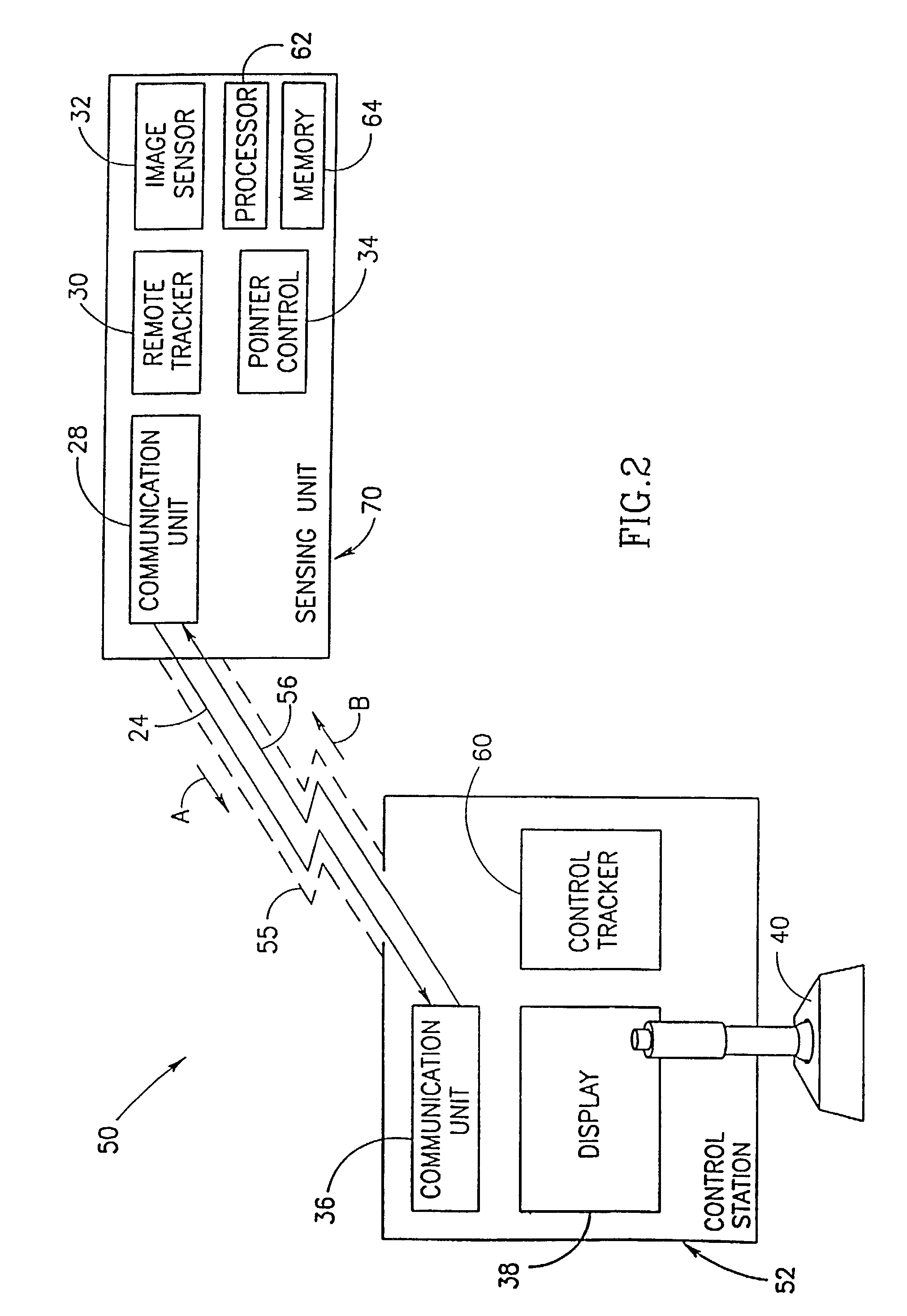
[0039]Reference is now made to FIG. 2, an illustration of a tracking system 50, constructed and operative in accordance with a preferred embodiment of the present invention. System 50 provides a reduced time delay by supplying the lock instructions directly from stick 40 to a local control tracker 60, in contrast to prior art which supplied the lock instructions to remote tracker 30. System 50 additionally provides improved tracking ability by supplying tracking instructions directly from control tracker 60 to sensor remote tracker 30, and thus providing more exact tracking / locking instructions than those experienced by prior art tracking systems.

[0040]Elements similar to system 10 are numbered similarly and have similar functions, and will not be described further hereinbelow.

[0041]In a preferred embodiment, system 50 comprises an image sensing unit 70 and a control station 52, which are connected via a communication link 55. Sensing unit 70 locates a desired object, and sends sens...


PUM


Abstract

A tracking apparatus including a sensor tracker and a control tracker (60). The sensor tracker is connected to a sensor which senses a scene having at least one object therein, the sensor tracker provides sensor movement instructions to the sensor, enabling it track a selected object. The control tracker is located remotely from and communicates with the sensor tracker. Additionally, the control tracker takes measurements regarding the selected object and provides tracking instructions to the sensor tracker. The sensor tracker then utilizes the tracking instructions to adjust the sensor movement instructions, when necessary.

Description

FIELD OF THE INVENTION[0001]The present invention relates to tracking systems in general, and to delayed tracking systems in particular.BACKGROUND OF THE INVENTION[0002]In many applications, an operator controls a remote image sensor via a communication link. Typical operator controlled applications are traffic control, border control, search and rescue operations, land surveys, police surveillance, etc. Operators may additionally request measurements of the remote tracked object, such as motion parameter measurements and the like.[0003]Reference is now made to FIG. 1, which illustrates a prior art surveillance / tracking system 10, comprising a remote image-sensing unit 20 and a control center 22, which are connected via a communication link 25.[0004]Sensing unit 20 comprises a sensor communication unit 28, a remote tracker 30, an image sensor 32, and a pointer control unit 34. The methods of operation for these elements are well known in the art. Sensing unit 20 locates and tracks a...

Claims


Application Information

Patent Timeline
Patent Type & Authority Patents(United States)
IPC IPC(8): G06K9/00G01S3/786G02BH04N5/225H04N5/232
CPCG01S3/7864G06T7/2033H04N5/23203G06T2207/30196G06T2207/30236G06T2207/10016G06T7/246H04N23/66
Inventor ZAHAVI, DOV
Owner RAFAEL ADVANCED DEFENSE SYSTEMS
Why Eureka
Try Eureka