Energizable electrical test device for measuring current and resistance of an electrical circuit

a technology of electrical circuit and current resistance, which is applied in the direction of electric devices, instruments, transportation and packaging, etc., can solve the problems of inability to test such electrical systems in the powered state, logic probes typically are incapable of measuring specific voltage levels, and the complexity of motor vehicles is increasing

Active Publication Date: 2007-02-27
POWER PROBE
View PDF35 Cites 28 Cited by
  • Summary
  • Abstract
  • Description
  • Claims
  • Application Information

AI Technical Summary

Benefits of technology

[0006]Provided is a uniquely configured electrical test device that is specifically adapted to provide current sourcing to an electrical system while also providing multi-meter functionality for selective measurement of a plurality of parameters of the electrical system under test. In addition to functions commonly performed by multi-meters, the electrical test device includes the capability to characterize loaded impedance, wave form and current drain. The unique configuration of the electrical test device eliminates the need for a clip-on current sensor as may be used in prior art electrical test devices to measure A.C. and D.C. current in a current carrying conductor of the electrical system under test. In addition, the unique configuration of the electrical test device eliminates the need for a separate power cable and probe element connection.

Problems solved by technology

Much of the increased complexity of motor vehicles is due in part to the increased complexity of electrical circuitry and systems incorporated therein.
Troubleshooting and diagnosing problems with such electrical systems requires the use of a wide array of complex test equipment.
Unfortunately, such logic probes typically are incapable of measuring specific voltage levels.
Another drawback associated with prior art test equipment regards the inability to test such electrical systems in the powered state.
More specifically, many existing multi-meters and logic probes are incapable of diagnosing problems with the circuitry in the operating mode such as testing electrical systems of a motor vehicle in the inoperative state.
For example, certain electrical devices in the electrical system of an automobile having a non-operational engine cannot be tested in the normal operating mode.
Unfortunately, unless power is provided to the fan motor using a separate power source, it is impossible to test and diagnose certain problems with the fan motor.

Method used


Image

  • Energizable electrical test device for measuring current and resistance of an electrical circuit
  • Energizable electrical test device for measuring current and resistance of an electrical circuit
  • Energizable electrical test device for measuring current and resistance of an electrical circuit

Examples


Embodiment Construction

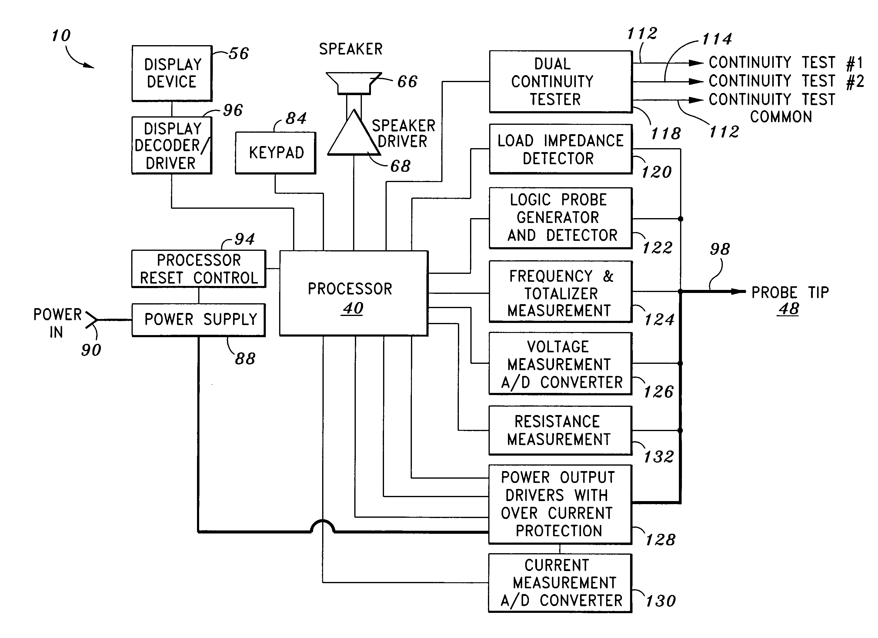
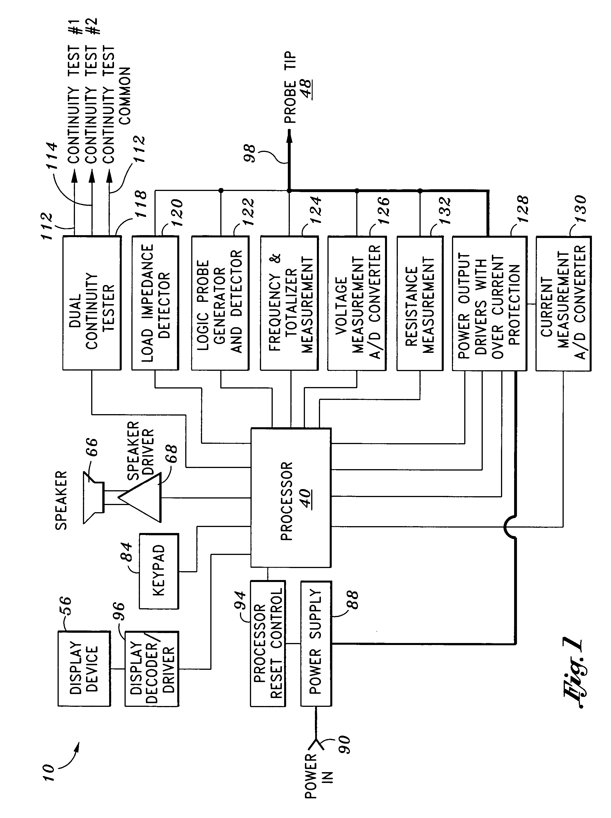
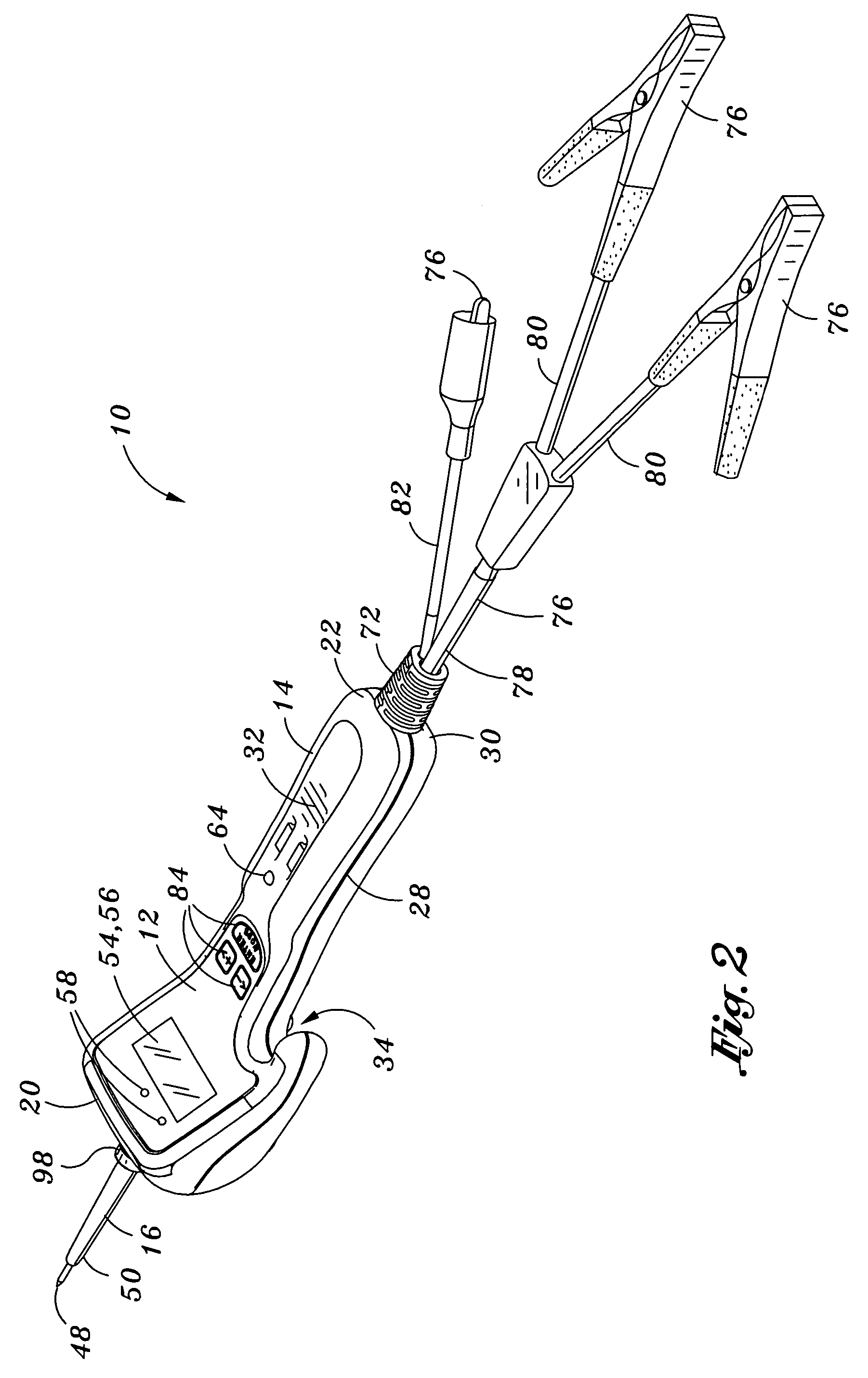
[0017]Referring now to the drawings wherein the showings are for purposes of illustrating various aspects of the invention and not for purposes of limiting the same, provided is a uniquely configured electrical test device 10 that is specifically adapted to provide current sourcing to an electrical system while also providing multi-meter functionality for selective measurement of a plurality of parameters of the electrical system. Advantageously, the electrical test device 10 is uniquely configured to allow for the collection of data on active, even on relatively high-current, electrical systems.

[0018]More specifically, the electrical test device 10 is specifically configured to allow access to current flow through the electrical system and includes the capability to characterize loaded impedance, wave form (e.g., fluctuation, frequency / speed), and current drain in addition to functions commonly performed by multi-meters such as voltage, current and resistance measurements. As was e...


PUM


Abstract

Provided is an electrical test device having multi-meter functionality and being adapted to provide current sourcing to an electrical system for selective measurement of a plurality of parameters. The electrical test device comprises a conductor probe element, a power supply, a processor and a display device. The power supply is interconnected between an external power source and a probe element. The processor is connected to the probe element and is configured to provide an input signal to the electrical system and receive an output signal in response thereto. The output signal is representative of at least one of the parameters of the electrical system. The display device is configured to display reading the output signal which is representative of the parameter. The electrical device is configured to allow for selective powering of the electrical system upon energization of the probe element during measurement of the parameters.

Description

CROSS-REFERENCE TO RELATED APPLICATIONS(Not Applicable)STATEMENT RE: FEDERALLY SPONSORED RESEARCH / DEVELOPMENT(Not Applicable)BACKGROUND OF THE INVENTION[0001]The present invention relates to electrical test equipment and, more particularly, to an electrical test device adapted to apply power to and perform multiple measurements upon an electrical system in the powered state.[0002]Motor vehicles such as automobiles and trucks are becoming increasingly technologically sophisticated requiring a correspondingly more sophisticated set of test equipment for maintenance and diagnostic testing. Much of the increased complexity of motor vehicles is due in part to the increased complexity of electrical circuitry and systems incorporated therein. Troubleshooting and diagnosing problems with such electrical systems requires the use of a wide array of complex test equipment.[0003]Such test equipment may include, for example, devices commonly referred to as multi-meters and which are configured t...

Claims


Application Information

Patent Timeline
Patent Type & Authority Patents(United States)
IPC IPC(8): G06F3/02
CPCG01R15/125
Inventor CRUZ, RANDY
Owner POWER PROBE
Why Eureka
Try Eureka