Tubular skylight for lighting rooms with natural light

a technology of natural light and skylight, which is applied in the direction of photovoltaics, building components, lighting and heating apparatus, etc., can solve the problems of reducing the function of the currently provided refracting prism with respect to the potential of rays, and allowing the acquisition of prisms, so as to achieve the effect of optimizing sunlight collection

Active Publication Date: 2007-03-06
BRACALE GENNARO
View PDF32 Cites 32 Cited by
  • Summary
  • Abstract
  • Description
  • Claims
  • Application Information

AI Technical Summary

Benefits of technology

[0005]The aim of the present invention is to eliminate the above mentioned drawbacks, by providing a tubular skylight for lighting rooms with natural light that allows to optimize sunlight collection, particularly as regards the rays reflected by the mirror-finished surface.
[0006]Within this aim, a particular object of the invention is to provide a skylight in which it is possible to increase significantly the quantity of rays diverted by refraction, by way of the possibility to optimize the shape of the prisms with respect to the source of the rays and the shape of the tubular element.
[0007]Another object of the present invention is to provide a tubular element that can be easily coupled to the light diffuser arranged inside the room, thus optimizing the quantity of rays that is introduced and also simplifying all production work.
[0008]Another object of the present invention is to provide a tubular skylight which thanks to its particular constructive characteristics is capable of giving the greatest assurances of reliability and safety in use and is further competitive from a merely economical standpoint.

Problems solved by technology

The constructive solutions that are adopted currently do not allow to obtain prisms with a correct angle, since said prisms are provided directly on the surface of the dome, which is usually inclined, and therefore the function of currently provided refracting prisms is reduced significantly with respect to the potential of the rays that can be collected.

Method used


Image

  • Tubular skylight for lighting rooms with natural light
  • Tubular skylight for lighting rooms with natural light
  • Tubular skylight for lighting rooms with natural light

Examples


Embodiment Construction

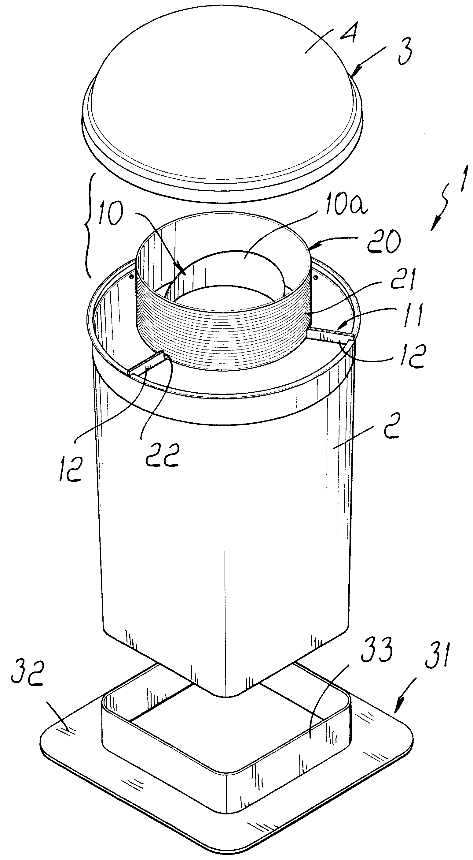
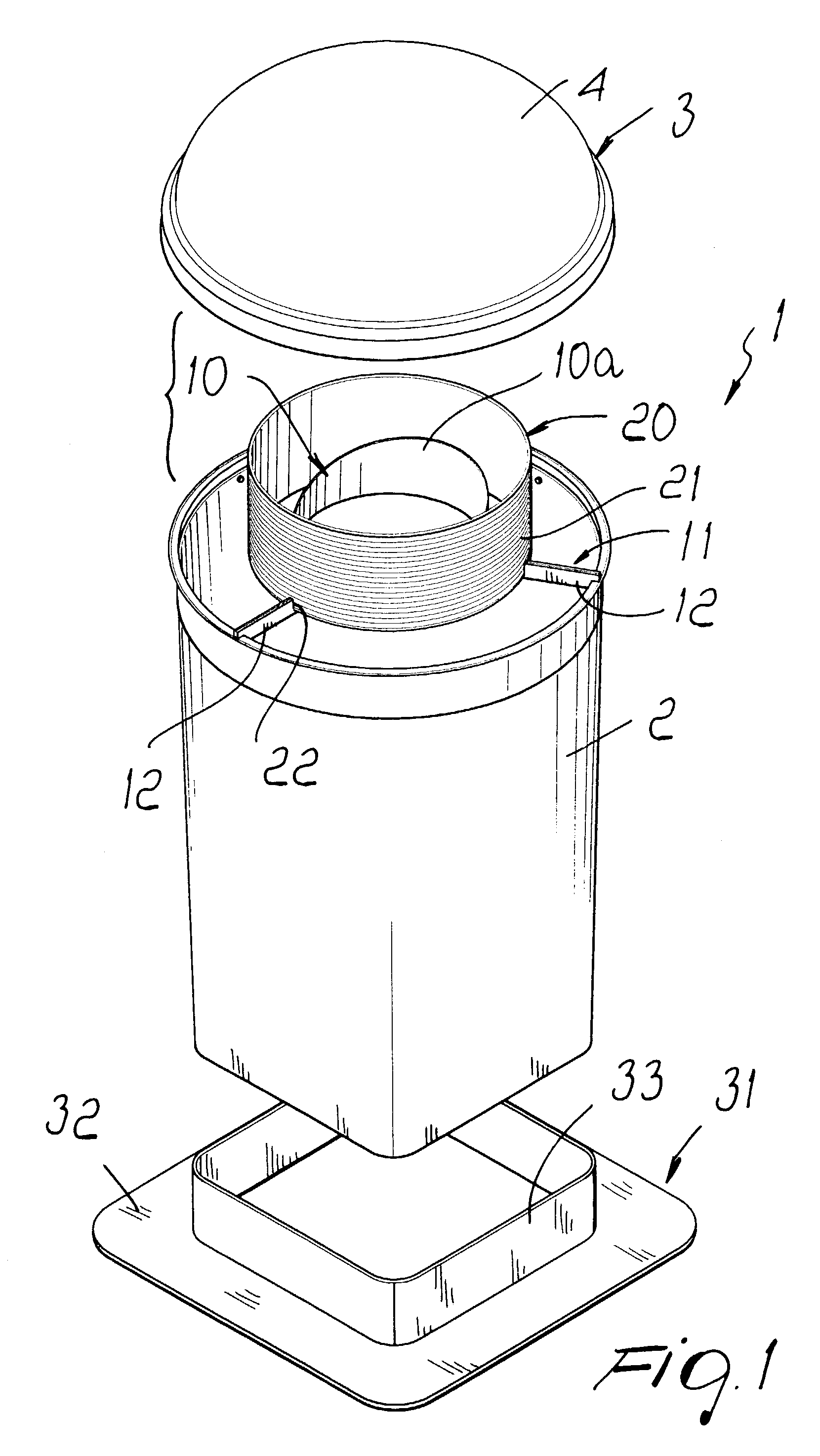
[0018]With reference to the figures, the tubular skylight for lighting rooms with natural light according to the invention, generally designated by the reference numeral 1, comprises a tubular body 2 with a reflective internal surface, which is provided so as to lead, at its lower end, into the room to be lit and has, at its other end or external end, a collector assembly generally designated by the reference numeral 3.

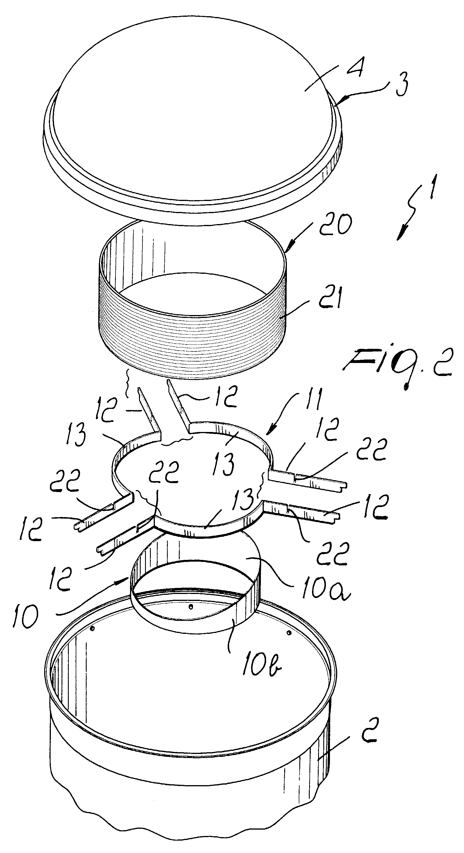
[0019]The collector assembly, as shown more clearly in FIG. 2, has an optically transparent dome 4, which is arranged so as to close the upper end of the tubular element 2 and internally encloses a mirror-finished body 10, which is advantageously formed by a cylindrical band in which the inner surface 10a and the outer surface 10b are both mirror-finished.

[0020]Advantageously, the body 10 has an axial width that can vary gradually from a point of minimum width to a point of maximum width, which are arranged at right angles to each other.

[0021]The mirror-finished body ...


PUM


Abstract

A tubular skylight for lighting rooms with natural light, comprising a tubular body with a reflective inner surface which leads into a room and has, at its external end, a natural light collector assembly and, at its internal end, a light diffuser. The collector assembly comprises, inside an optically transparent dome arranged so as to close the tubular body, a mirror-finished body which is substantially shaped like a cylindrical band with mirror-finished inner and outer surfaces. The axial width of the band-like body varies gradually from a minimum-width point to a maximum-width point, which lie diametrically to each other. It is also possible to provide a cylindrical refracting body that surrounds said mirror.

Description

BACKGROUND OF THE INVENTION[0001]The present invention relates to a tubular skylight for lighting rooms with natural light.[0002]It is known that tubular skylights for lighting rooms with natural light are already commercially available which generally have a tubular body with a reflective internal surface which has, at its upper end, a natural light collector assembly, which is generally constituted by an optically transparent dome-like body which internally encloses a mirror arranged so as to optimize sunlight collection.[0003]The mirror that is currently used has a prism-like shape and is capable of reflecting rays that arrive from a single direction, since the mirror is arranged proximate to one edge of the tubular element. Moreover, in order to increase the incoming light, prism-like surfaces are formed on the dome which facilitate the redirection of the rays that otherwise would not enter the tubular element.[0004]The constructive solutions that are adopted currently do not al...

Claims


Application Information

Patent Timeline
Patent Type & Authority Patents(United States)
IPC IPC(8): E04D13/03E04D13/18F21S11/00F21V5/02
CPCE04D13/033F21V13/04F21V5/02F21V7/0091F21S11/00E04D2013/0345
Inventor BRACALE, GENNARO
Owner BRACALE GENNARO
Why Eureka
Try Eureka