
Inductive heating magnetic structure for removing condensates from electrical smoking device

a technology of inductive heating and magnetic structure, which is applied in the direction of induction heating, electric/magnetic/electromagnetic heating, tobacco, etc., can solve the problems of detracting from the flavor and overall pleasure of the user of the device, the functionality of the smoking device, and the condensate may form and collect on the heating fixture, so as to improve the heating effect and increase the heating power , the effect of reducing power

Active Publication Date: 2007-03-06
PHILIP MORRIS USA INC
View PDF15 Cites 170 Cited by
  • Summary
  • Abstract
  • Description
  • Claims
  • Application Information

AI Technical Summary

Benefits of technology

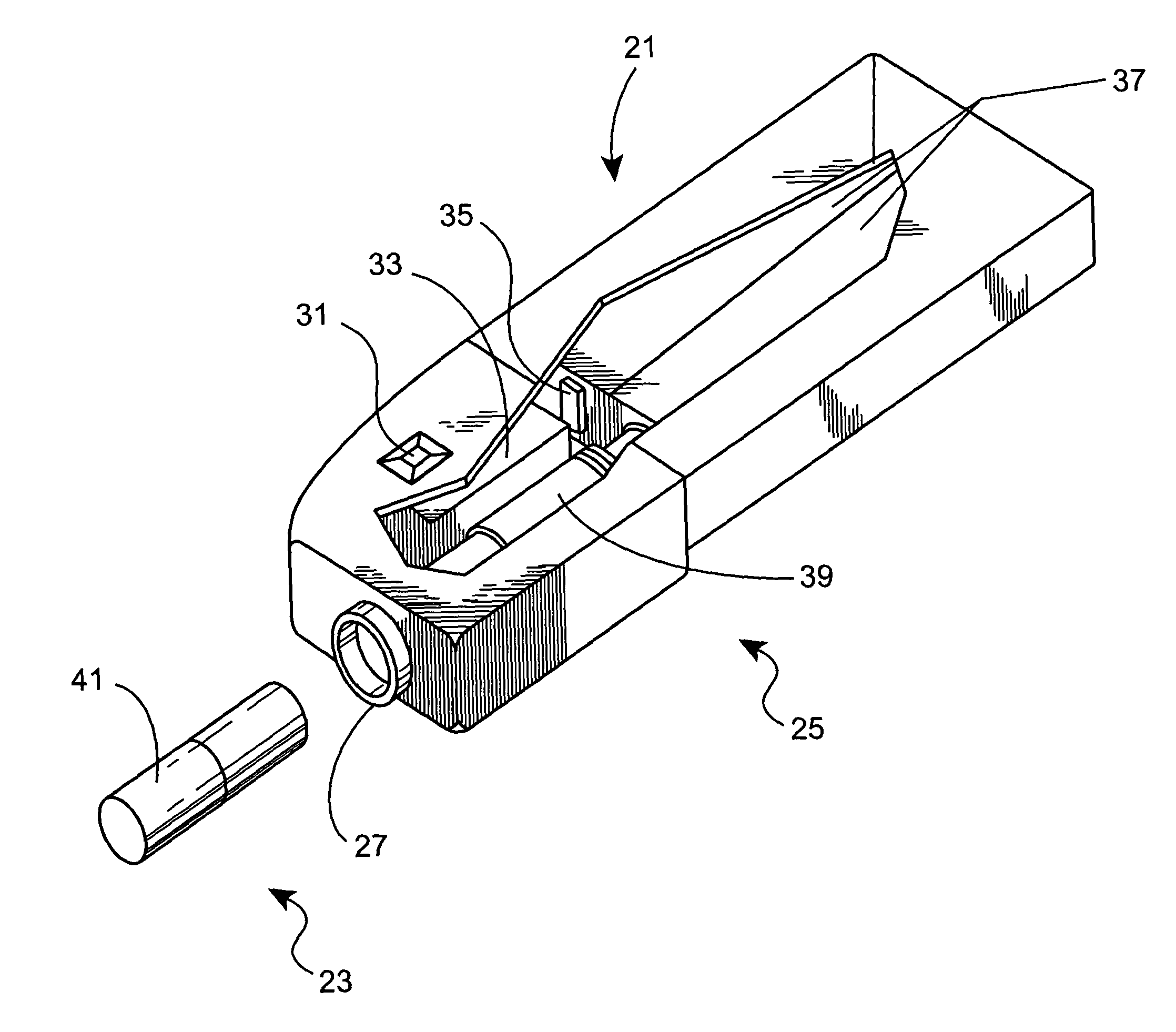
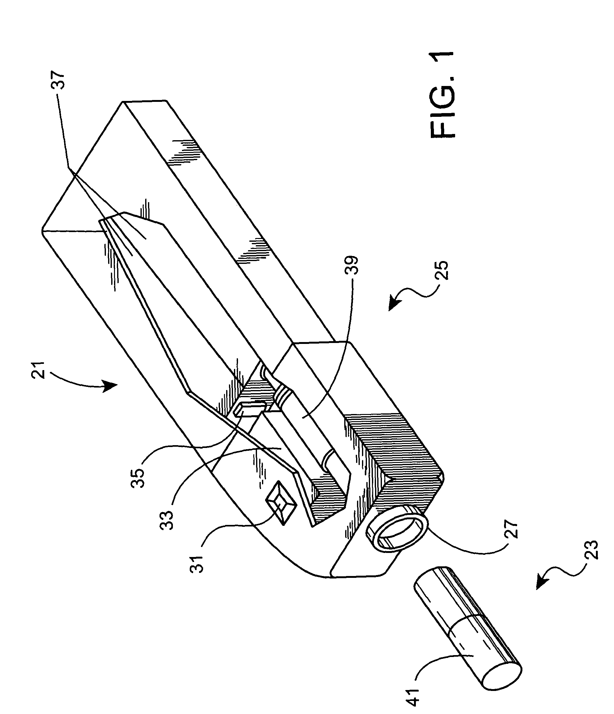
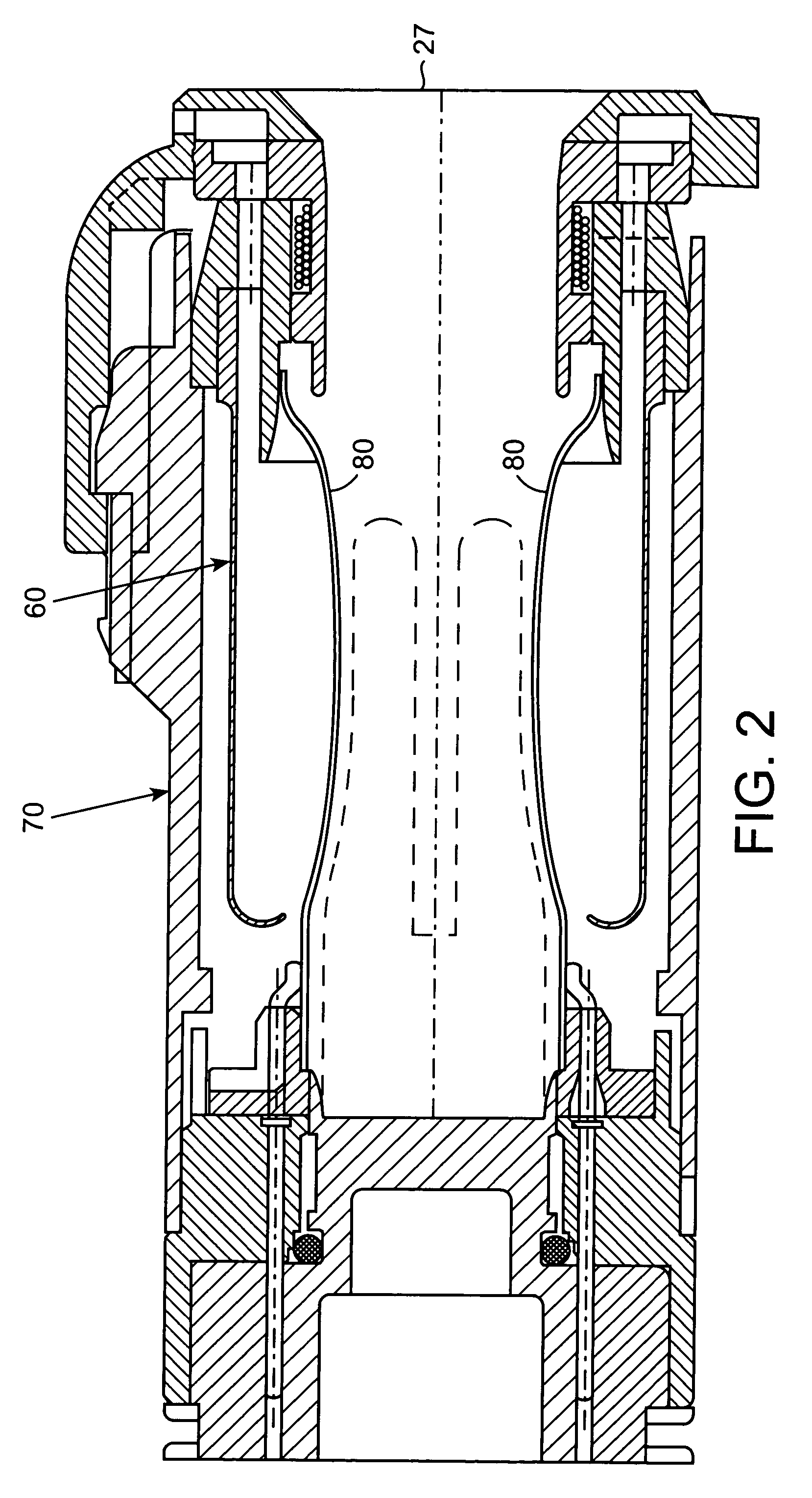
[0007]The present invention provides methods and apparatus that enhance inductive heating techniques for the purpose of removing condensates formed within an electrically heated cigarette smoking device. Embodiments of the present invention include a magnetic shell that surrounds inductive heating elements such as radio-frequency excitation coils, which induce electrical current in metallic components of the smoking device. The metallic components, such as a cylindrical canister positioned around the heater blades for the purpose of directing air flow and capturing condensates that are not inhaled by the user, constitute the heating target. The induced electrical current heats the components and volatilizes any condensates that may be collected on the compo

Problems solved by technology

As a result, condensates may form and collect on the heating fixture.
The build up of condensates can affect the functionality of the smoking device and may detract from the flavor and overall pleasure experienced by a user of the device.
However, activation of the heating elements may not fully clean the condensates located on other components within the device.
However, conventional systems for cleaning the smoking device with the aid of a catalyst have required separate heaters and circuitry for heating the catalyst, which can increase costs and the size of the cleaning system while reducing efficiency.

Method used


Image

  • Inductive heating magnetic structure for removing condensates from electrical smoking device
  • Inductive heating magnetic structure for removing condensates from electrical smoking device
  • Inductive heating magnetic structure for removing condensates from electrical smoking device

Examples


Embodiment Construction

[0017]Inductive heating techniques provide the user of an electrical smoking device the ability to efficiently liberate the smoking device from condensates that may build up in the device during normal use. When used in conjunction with a cleaning module, the smoking device can be sufficiently cleansed of the liberated condensates in a environmentally friendly manner. The cleaning module can include an inductive coil of consistent or varying configuration that can be placed around a target, such as a circular tube or canister, and driving circuitry provided to maintain resonant circuit conditions for maximizing efficiency and power transfer to the excitation coils. The driving circuitry should be able to create enough power to sufficiently heat the target, which can be in the form of a canister positioned around an arrangement of electrical heater blades. When power is delivered to the inductive coils, electromagnetic flux is created that passes through the canister. The flux causes...


PUM


Abstract

Thermal cleaning of an electrically heated smoking device, and in particular the removal of condensates formed within the smoking device as a result of extended periods of use, is achieved with a cleaning system that utilizes inductive heating that provides efficient and intense localized heating in the cleaning process. The thermal power of the inductive heating process is increased or the power necessary to activate the inductive heating process is decreased by the addition of a magnetic shell by itself or in combination with a magnetic pin.

Description

TECHNICAL FIELD OF THE INVENTION[0001]The present invention relates to methods and apparatuses for using, cleaning and maintaining heat sources used in electrical smoking systems.BACKGROUND OF THE INVENTION[0002]Commonly assigned U.S. Pat. Nos. 5,388,594; 5,505,214; 5,530,225; and 5,591,368 disclose various electrically powered smoking systems comprising cigarettes and electric lighters and are hereby expressly incorporated by reference.[0003]The smoking systems referred to above are designed with the intention of providing the user with all the pleasures of smoking while significantly reducing the side stream smoke produced during smoking. The smoking system also allows users the added benefit of reinitiating smoking of a cigarette that has been partially smoked, thereby providing the smoker with the ability to suspend and reinitiate smoking as desired.[0004]In the operation of the smoking system a non-traditional cigarette is inserted in a heating fixture and heating elements are ...

Claims


Application Information

Patent Timeline
IPC IPC(8): A24F3/02A24F40/20A24F40/465A24F40/50A24F40/85H05B6/10
CPCH05B6/105A24F47/008A24F40/465A24F40/50A24F40/85A24F40/20
Inventor SHARPE, DAVID E.
Owner PHILIP MORRIS USA INC
Learn More