Composite shoulder prosthesis

a shoulder and joint technology, applied in the field of joint prosthesis, can solve the problems of four parts not being able to unite with the rest of the humerus, inability to stabilize the fragment, and inability to be positioned in an inappropriate position

Inactive Publication Date: 2007-03-06
CYPRIEN JEAN MAXWELL +4
View PDF13 Cites 9 Cited by
  • Summary
  • Abstract
  • Description
  • Claims
  • Application Information

AI Technical Summary

Benefits of technology

[0029]Embodiments of the invention are described in more d...

Problems solved by technology

This results in the four parts fractures described by Neer.
However, if replacing the humeral head is relatively easy, reattaching the tuberosities often results in failure of those parts to unite to the rest of the humerus or in their union in...

Method used


Image

  • Composite shoulder prosthesis
  • Composite shoulder prosthesis
  • Composite shoulder prosthesis

Examples


Embodiment Construction

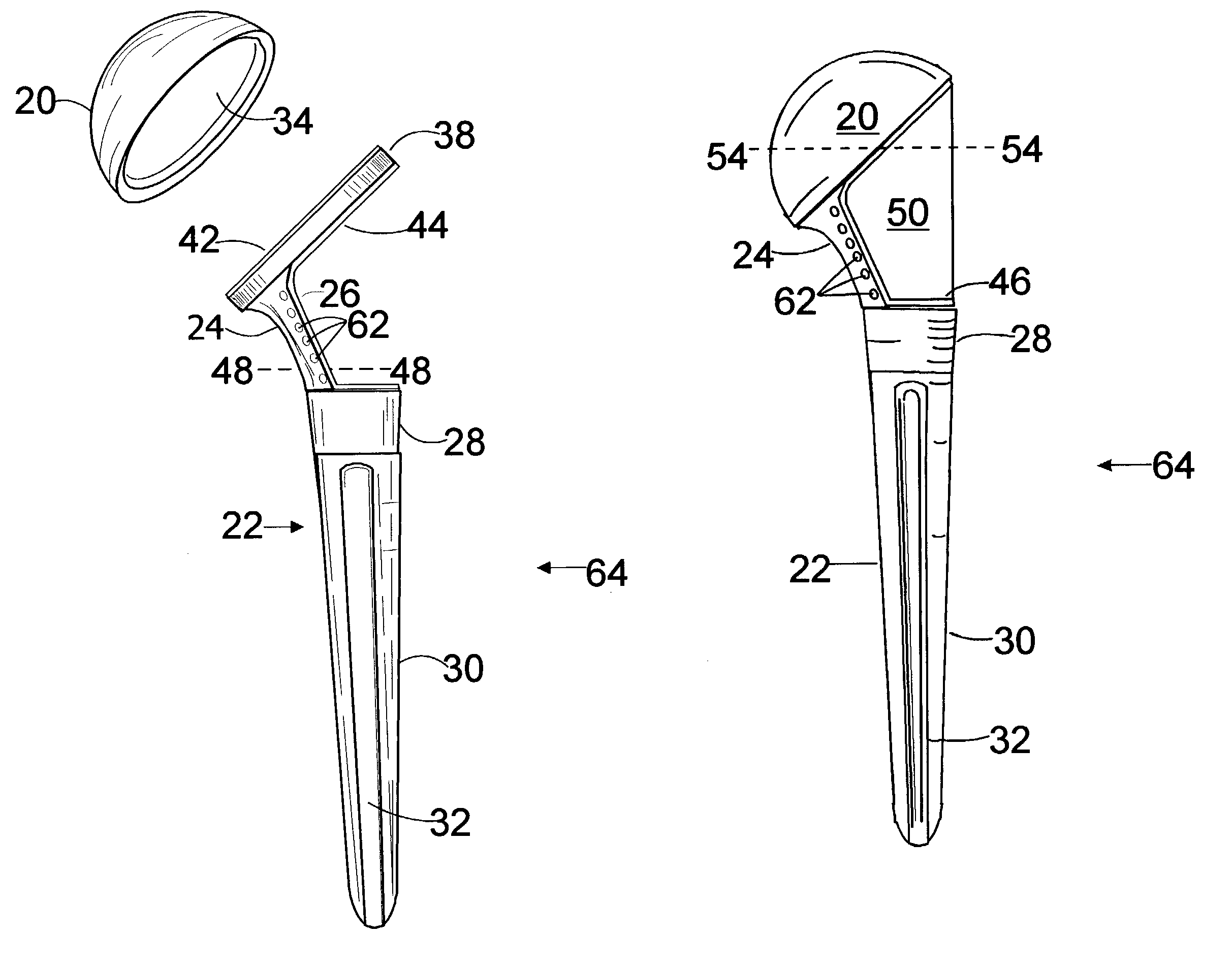
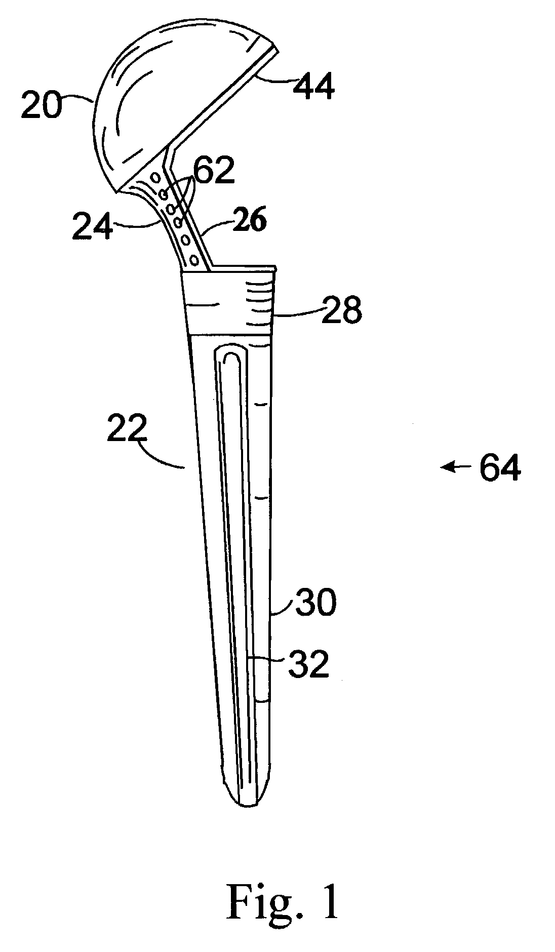
[0042]FIG. 1 shows the shoulder prosthesis 64 according to the invention. It is made of a head, which is a generally spherical cap 20 and a stem 22 with a medial pillar 24 with on its lateral aspect a coating of a material 26 that allows for bone ingrowth and holes 62 to attach an iliac bone graft and the tuberosities.

[0043]The stem 22, on its most upper part 28, is coated with a material that allows for bone ingrowth and its lower part 30 is made of metal to allow cementation. It has longitudinal grooves 32 to facilitate cementation.

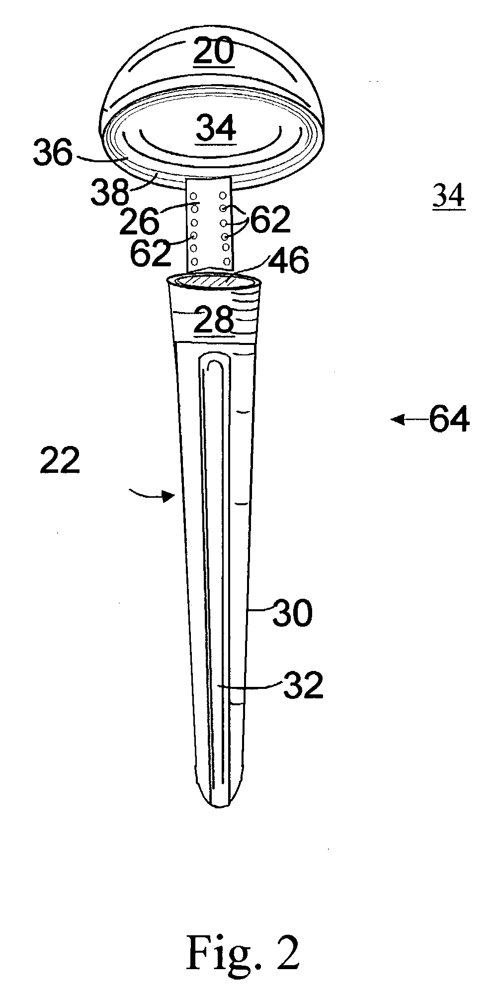
[0044]FIG. 2 is a right elevational view of the prosthesis 64 showing the inner lining 34 of the spherical cap 20, the inner lining 36 of the ring 38, of the medial pillar 26, the coating of the upper part 28 of the stem 22 and its slightly hollow coated superior aspect 46.

[0045]FIG. 3 is a left elevational view of the prosthesis 64 showing the medial aspect of the spherical cap 20 and of the medial pillar 24.

[0046]FIG. 4-A shows parts of the prosthesis...


PUM


Abstract

The invention is a modular composite shoulder prosthesis 64, whose construct incorporates a solid autogenous bone graft 50 to be used to replace the upper humerus in certain fracture types. The prosthesis comprises a stem 22 to be inserted in the canal of the humerus, an intermediary part reduced to a medial pillar 24 and a head which is a generally spherical cap 20 that is hollow. The head of the prosthesis being hollow and coated with an osteoconductive material, the lateral aspect of the medial pillar as well as the upper part of the stem being also coated with the same material, an epiphyso-metaphyseal space is delineated in which a solid autogenous bone graft is fitted. Union can be achieved between the coated parts of the prosthesis, the bone graft 50 and the tuberosities reattached to the humerus shaft, secured to holes 62 of the medial pillar and between themselves.

Description

CROSS-REFERENCES TO RELATED APPLICATIONS[0001]U.S. Pat. DOCUMENTS6,334,874Tornier, et al.Jan. 1, 20026,406,496RuterJun. 18, 20026,398,812MasiniJun. 4, 20026,368,352Camino, et alApr. 9, 20026,171,341Boileau et al.Jan. 9, 20015,944,758Mansat, et alAugust 19993,228,393MicheleJan. 11, 1966FOREIGN PATENT DOCUMENT:DE 4220217Ruether, et alDec. 23, 1993FEDERALLY SPONSORED RESEARCH[0002]Not applicableSEQUENCE LISTING OR PROGRAM[0003]Not applicableBACKGROUND OF THE INVENTION[0004]Replacement of diseased or injured joints is common practice in orthopedic surgery. The replacement of a shoulder joint either for arthritic disease or for fracture by an artificial device can restore function in many cases.[0005]Shoulder prostheses can be implanted in the presence of the so-called “four part humeral fractures”. In those fractures of the proximal part of the humerus, the humeral head, the greater tuberosity and the lesser tuberosity separate from the humeral shaft. This results in the four parts frac...

Claims


Application Information

Patent Timeline
IPC IPC(8): A61F2/40A61F2/00A61F2/28A61F2/30
CPCA61F2/40A61B17/842A61F2/30767A61F2002/2817A61F2230/0065A61F2002/30604A61F2002/3082A61F2002/4025A61F2002/4037A61F2002/302A61F2002/30593
Inventor CYPRIEN, JEAN-MAXWELLBURDET, ANDREDEMOTTAZ, JEAN-DOMINIQUEBONVIN, JEAN-CLAUDENEUHAUS, BERNARD
Owner CYPRIEN JEAN MAXWELL
Why Eureka
Try Eureka