Interposer with integral heat sink

a heat sink and interposer technology, applied in the field of interposers, can solve the problem of wasting a large amount of valuable circuit card area

Active Publication Date: 2007-03-06
AIRBORN
View PDF9 Cites 38 Cited by
  • Summary
  • Abstract
  • Description
  • Claims
  • Application Information

AI Technical Summary

Problems solved by technology

This interposer design wastes a large amount of valuable circuit card area and creates a problem with what is commonly called “current sharing”, i.e., the need to split the current nearly equally between all of the parallel electrical contacts.

Method used


Image

  • Interposer with integral heat sink
  • Interposer with integral heat sink
  • Interposer with integral heat sink

Examples


Embodiment Construction

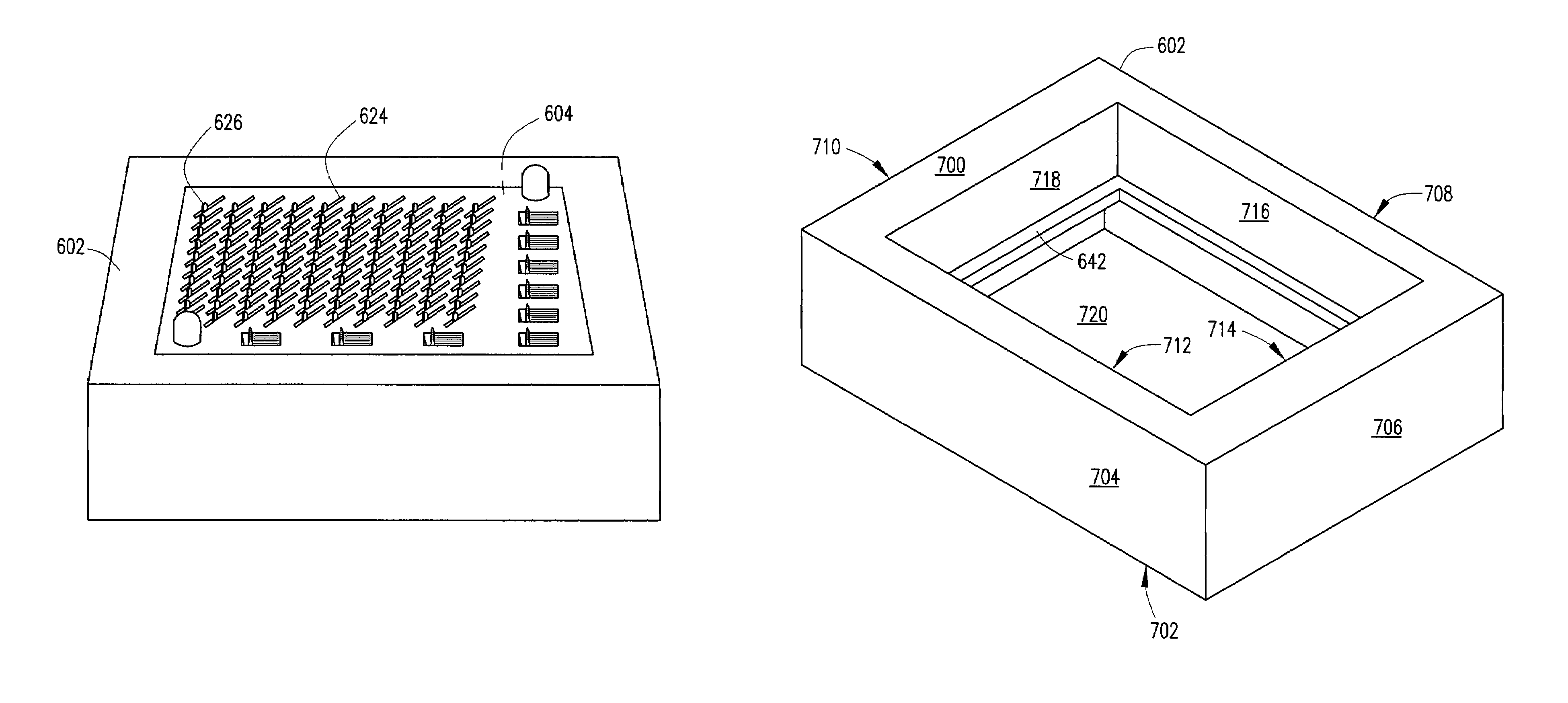
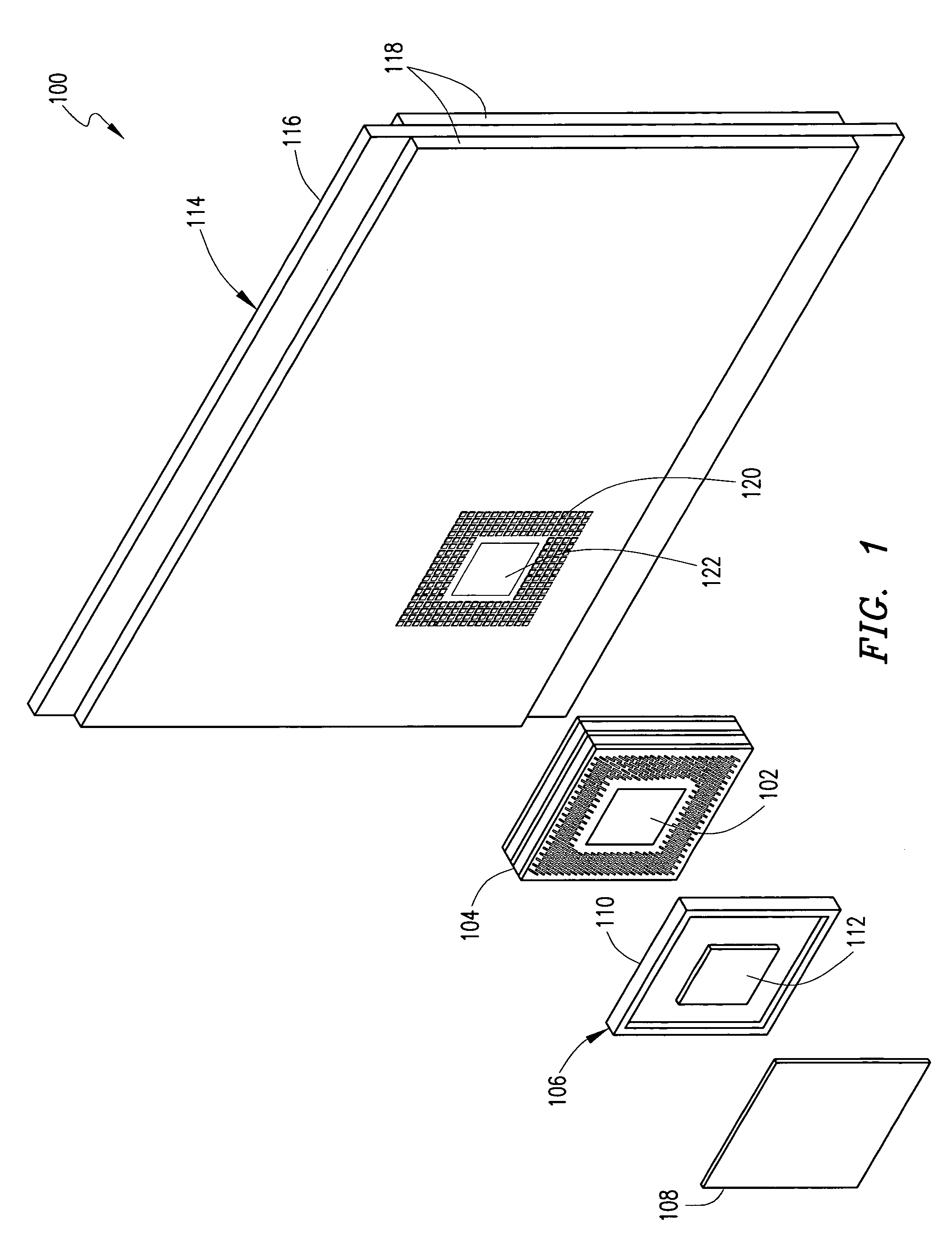
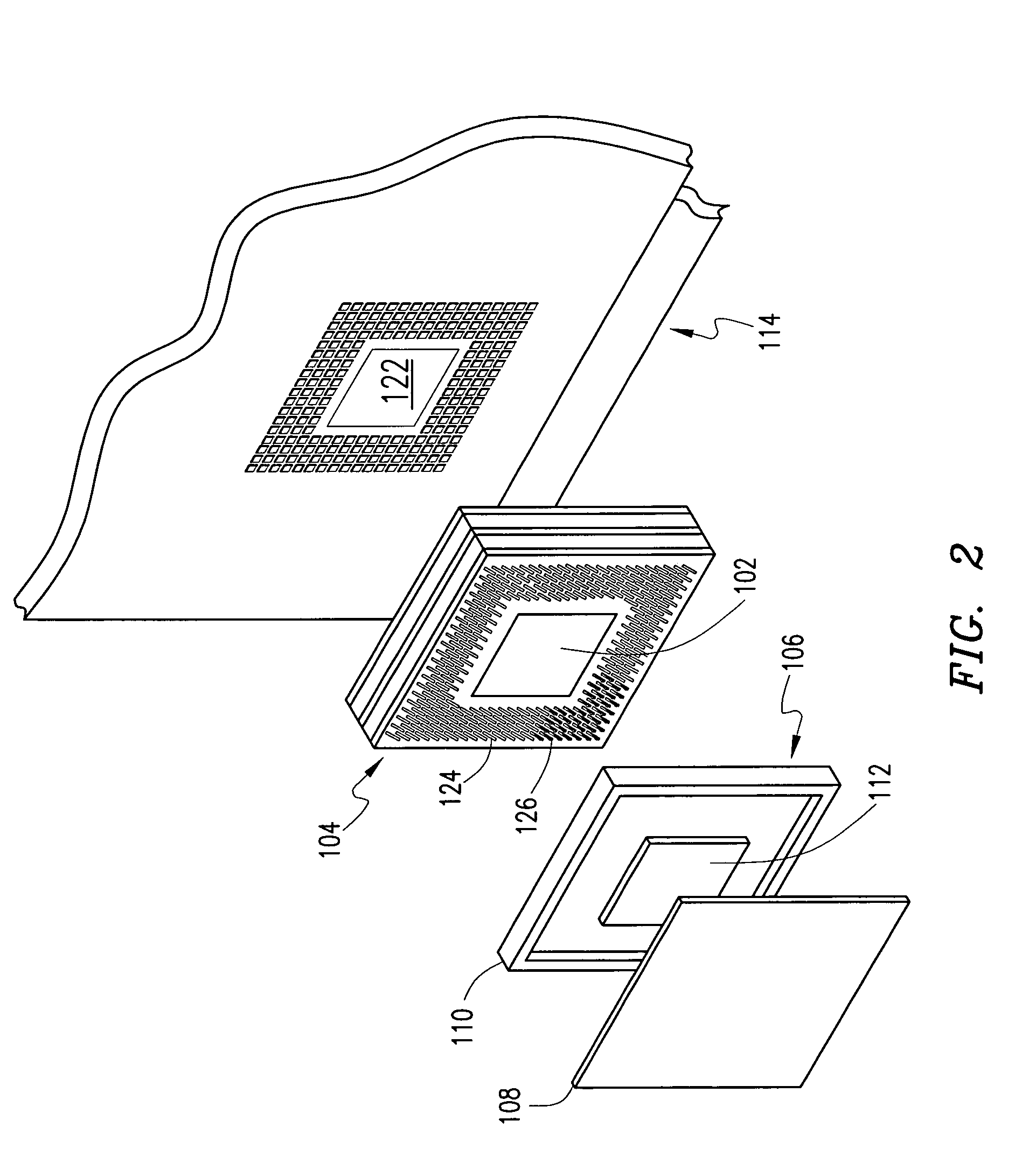
[0026]To improve the heat transfer from heat emitting elements, such as integrated circuits (ICs), a variety of heat dissipation techniques may be applied. In accordance with one embodiment of the present invention, as shown in FIG. 1, a system 100 may implement an integrated heat sink 102 and interposer 104. By including the heat sink 102 at a central portion of the interposer 104, the heat sink 102 improves the heat conduction from an IC package 106 through the system 100. The path of the heat flow from the heat emitting element (IC package 106) maximizes the conductivity of the conduction path and improves heat transfer.

[0027]The IC package 106 typically includes an outer ceramic shell 110 and an IC chip 112. The IC package 106 may be protected by a cover 108. The IC package 106 is connected electrically and thermally through the interposer 104 and the heat sink 102 to a printed wiring board (PWB) 114 which may then be integrated within an electronic device such as a flight contr...


PUM


Abstract

An area array connector for providing a thermal and an electrical interconnection between a first circuit element and a second circuit element is described. The area array connector includes at least one electrically conductive interconnector adapted to provide an electrical interconnection between the first circuit element and the second circuit element. The area array connector also includes at least one thermally conductive member adapted to provide thermal interconnection between the first circuit element and the second circuit element.

Description

CROSS-REFERENCE TO RELATED APPLICATIONS[0001]This Application claims the benefit under 35 USC 119(e) of U.S. Provisional Application No. 60 / 494,013, filed on Aug. 7, 2003.BACKGROUND OF THE INVENTION[0002]The present invention relates to interposers, such as area array connectors adapted for connecting the contact pads of one generally planar circuit element, such as a printed circuit board, to corresponding contact pads on another generally planar circuit element, such as an integrated circuit or multichip module, and more particularly, but not by way of limitation, to an interposer adapted for both electrical and thermal energy transfer therethrough.DESCRIPTION OF RELATED ART[0003]The manufacture of printed circuit boards, and more particularly, circuit board connectors, has expanded greatly over the past several decades. Both designs and fabrication techniques have improved to the point that ease in assembly and reliability of connection can almost be guaranteed. Not the least of ...

Claims


Application Information

Patent Timeline
Patent Type & Authority Patents(United States)
IPC IPC(8): H01L23/34H01L23/367H05K7/10
CPCH01L23/367H05K7/1053H01L2924/0002H01L2924/00
Inventor CUFF, MICHAEL P.GRANT, JOHN L.
Owner AIRBORN
Why Eureka
Try Eureka