
Solid oxide fuel cell

a fuel cell and solid oxide technology, applied in the manufacture of cell components, final product manufacturing, electrochemical generators, etc., can solve the problems of deteriorating output performance of solid oxide fuel cells using this material for the electrolyte membraneelectrolyte membrane, electrode and the electrolyte membrane cannot be efficiently promoted, and it is difficult to fabricate an electrolyte membraneelectrolyte membrane free of gas permeability

Active Publication Date: 2006-09-07
MORIMURA SOFC TECH CO LTD
View PDF5 Cites 29 Cited by
  • Summary
  • Abstract
  • Description
  • Claims
  • Application Information

AI Technical Summary

Benefits of technology

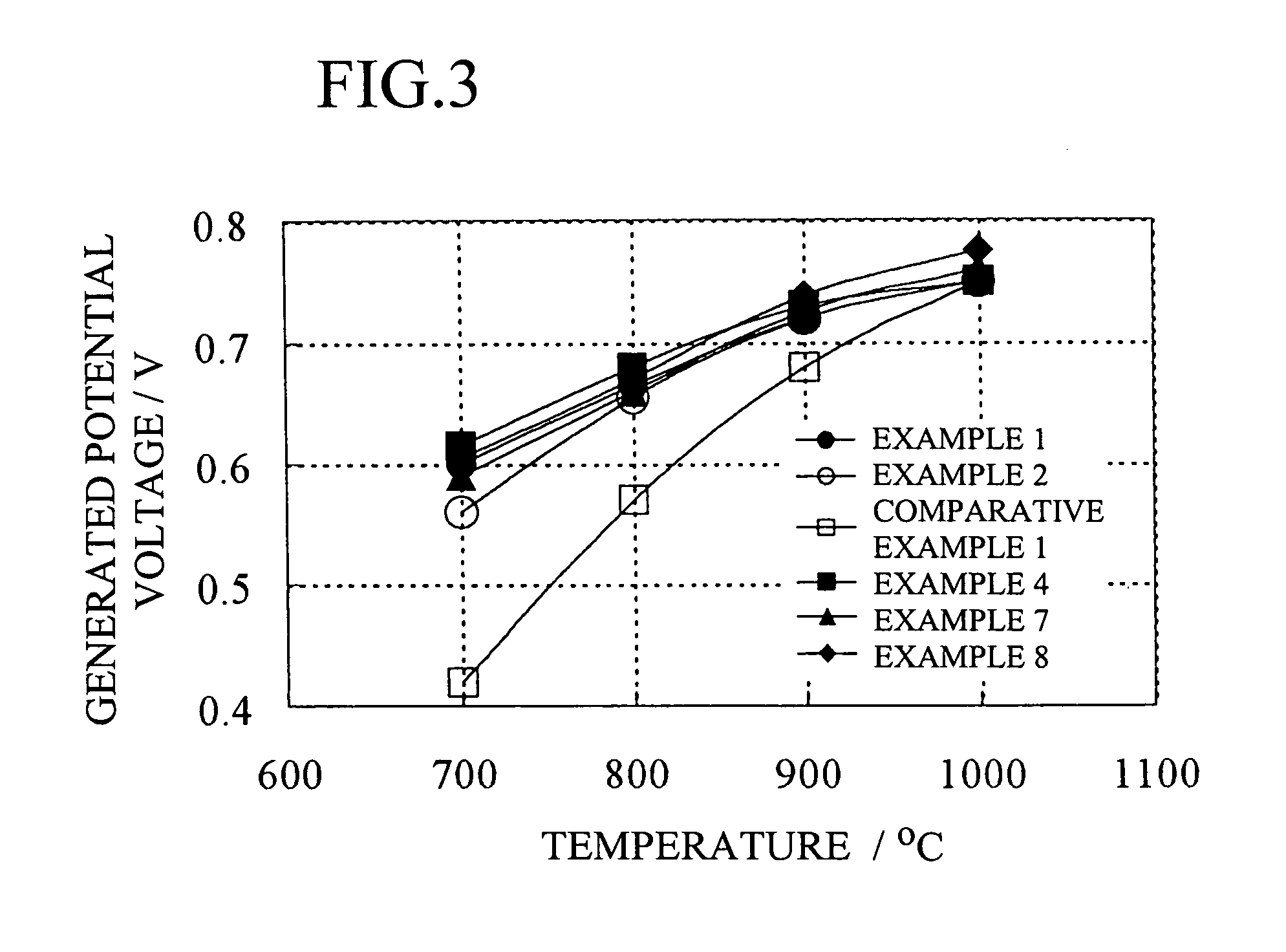
[0085] Since the present invention provides a solid oxide fuel cell comprising a single cell having an air electrode disposed on a surface of an electrolyte membraneelectrolyte membrane and a fuel electrode disposed on the other surface of the electrolyte membraneelectrolyte membrane, and an interconnector having a role of electrical connection; wherein the electrolyte membraneelectrolyte membrane is provided with a first layer composed of a material having an oxygen-ionic conductivity of S1 on the air-electrode side, a second layer composed of a material containing at least zirconia having an oxygen-ionic conductivity of S2 on the fuel-electrode side, and the oxygen-ionic conductivity of S1 on the air-electrode side and the oxygen-ionic conductivity of S2 on the fuel-electrode side have a relationship of S1>S2, a solid oxide fuel cell having excellent output performance can be provided.

Problems solved by technology

Since YSZ excels in sintering properties, it is possible to easily fabricate an electrolyte membraneelectrolyte membrane free of gas permeability; however, there has been a problem that the output performance of a solid oxide fuel cell using this material for the electrolyte membraneelectrolyte membrane is deteriorated because the oxygen-ionic conductivity of the electrolyte membraneelectrolyte membrane is decreased at low temperatures of 900° C. or below, and the reaction of Equation (1) occurring between the air electrode and the electrolyte membraneelectrolyte membrane cannot be efficiently promoted.
However, although the present inventors fabricated an electrolyte membraneelectrolyte membrane using the material described in Patent Document 2, as a result of the test conducted by the present inventors, it was difficult to fabricate an electrolyte membraneelectrolyte membrane free of gas permeability.
Since the material proposed in Patent Documents 3 and 4 has electronic conductivity in a fuel-gas environment of the solid oxide fuel cell, there has been a problem that the output performance is deteriorated if the electrolyte membraneelectrolyte membrane is composed of the proposed materials only.
When a manganese-containing oxide, such as lanthanum manganite, is adopted as the air electrode of the solid oxide fuel cell, electronic conductivity is produced in the material proposed in Patent Documents 5 and 6 due to diffusion of manganese components, and there has been a problem that the output performance is deteriorated if the electrolyte membraneelectrolyte membrane is composed of the proposed materials only.

Method used


Image

  • Solid oxide fuel cell
  • Solid oxide fuel cell
  • Solid oxide fuel cell

Examples


example 1

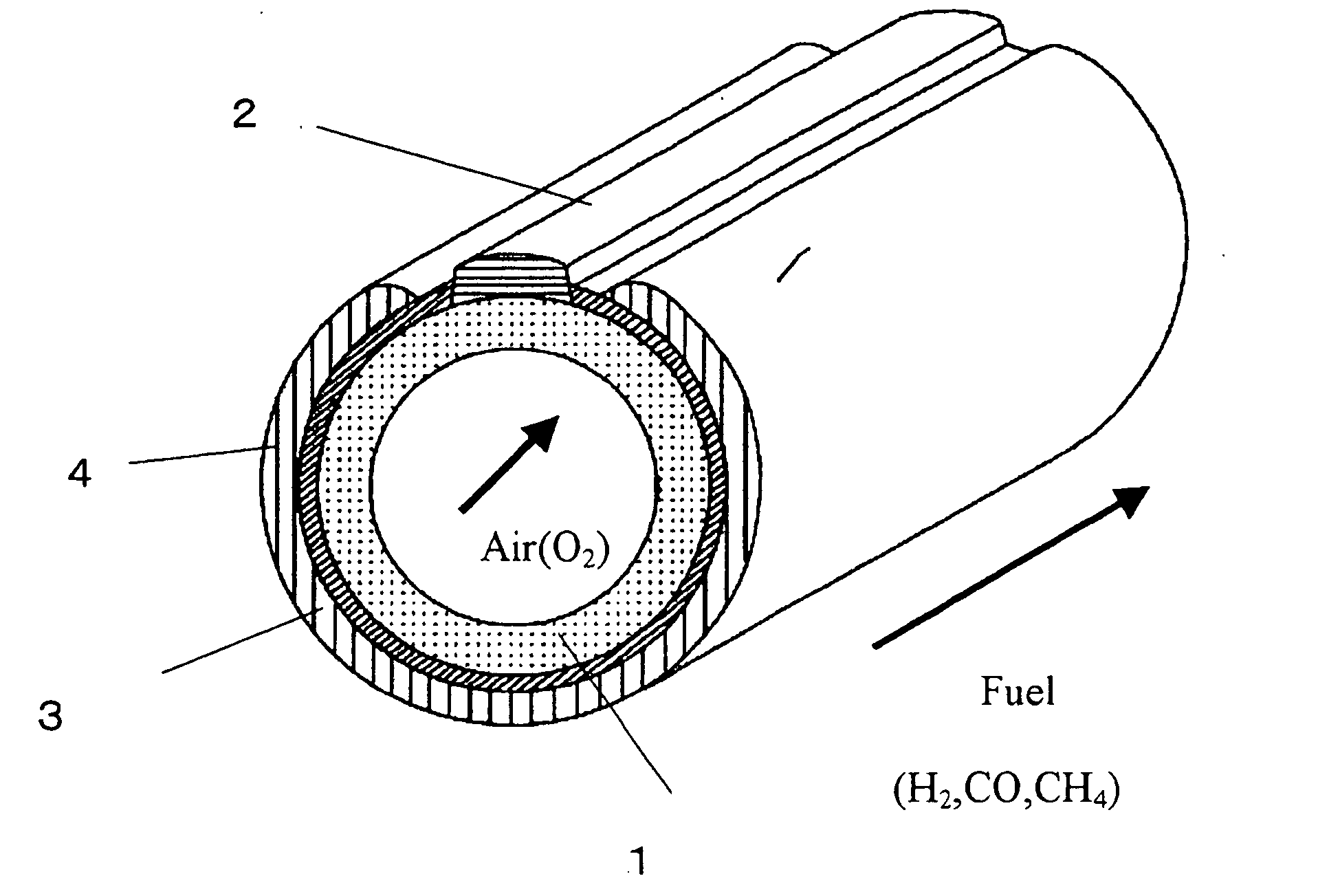
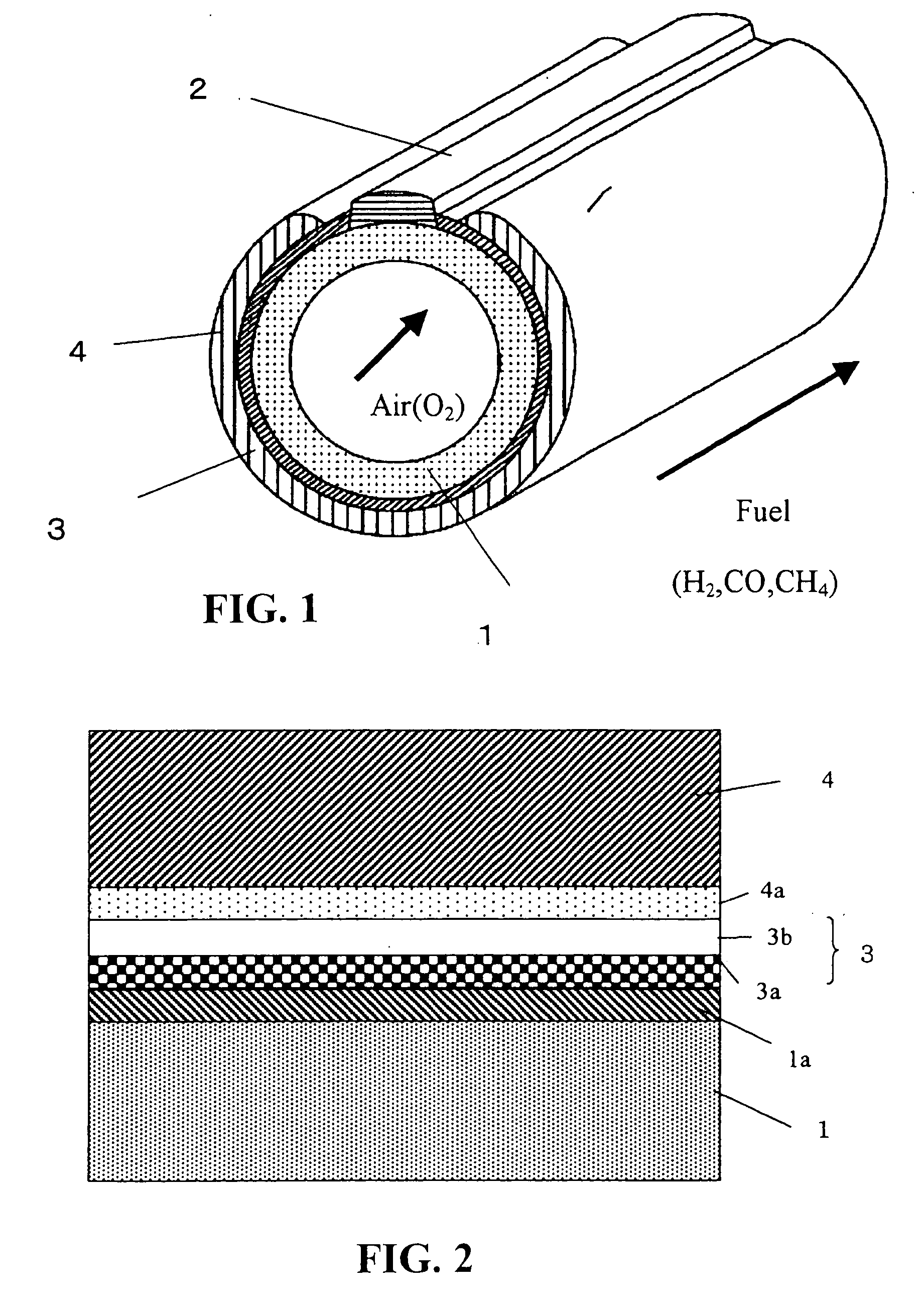
[0139] A cylindrical solid oxide fuel cell shown in FIG. 1 was used as a basic configuration. Specifically, the solid oxide fuel cell comprises an interconnector 2 and an electrolyte membrane 3 formed on a cylindrical air-electrode support 1, and a fuel electrode 4 formed on the electrolyte membrane 3 so as not to contact the interconnector 2. In Example 1, as shown in FIG. 2, the solid oxide fuel cell further comprises an electrode reaction layer formed between the air electrode and the electrolyte membrane, and a fuel-electrode-side reaction layer formed between the electrolyte membrane and the fuel electrode, in which the electrolyte membrane was composed of two layers.

(1) Fabrication of Air Electrode Support

[0140] The air electrode was composed of Sr-doped lanthanum manganite which is represented by a composition of La0.75Sr0.25MnO3, and the material powder for the air electrode was prepared by a co-precipitation method and then heat-treated. The average particle diameter was...

example 2

[0150] A solid oxide fuel cell was fabricated in the same manner as in Example 1 except that the material for the first layer was ScYSZ, and the composition was 90 mol % ZrO2-5 mol % Sc2O3-5 mol % Y2O3.

example 3

[0151] A solid oxide fuel cell was fabricated in the same manner as in Example 1 except that the material for the first layer was SSZ / YSZ, and the composition and the ratio were 90 mol % ZrO2-10 mol % Sc2O3 / 90 mol % ZrO2-10 mol % Y2O3=50 / 50; and the slurry was formed by adding 90 mol % ZrO2-10 mol % Sc2O3 powder of 20 parts by weight having an average particle diameter of 0.5 μm prepared by the above-described co-precipitation method, and 90 mol % ZrO2-10 mol % Y2O3 powder of 20 parts by weight having an average particle diameter of 0.5 μm prepared by the above-described co-precipitation method.


PUM


Abstract

The present invention provides an electrolyte membrane of a solid oxide fuel cell that excels in output performance. There is provided a solid oxide fuel cell comprising a single cell having an air electrode disposed on a surface of an electrolyte membrane and a fuel electrode disposed on the other surface of the electrolyte membrane, and an interconnector having a role of electrical connection; wherein the electrolyte membrane is provided with a first layer composed of a material having an oxygen-ionic conductivity of S1 on the air-electrode side, and a second layer composed of a material containing at least zirconia and having an oxygen-ionic conductivity of S2 on the fuel-electrode side; and wherein the oxygen-ionic conductivity of S1 on the air-electrode side and the oxygen-ionic conductivity of S2 on the fuel electrode side have a relationship of S1>S2.

Description

BACKGROUND OF THE INVENTION [0001] 1. Field of the Invention [0002] The present invention relates to a solid oxide fuel cell that excels in output performance. Specifically, the present invention relates to a solid oxide fuel cell having an electrolyte membraneelectrolyte membrane free of gas permeability that excels in oxygen-ionic conductivity, and having a high output performance even at a power-generating temperature of 900° C. or below. [0003] 2. Description of the Related Art [0004] As an electrolyte membraneelectrolyte membrane for a conventional solid oxide fuel cell, a layer composed of yttria-doped zirconia (hereafter referred to as YSZ) has been proposed. (For example, see Patent Document 1.) Since YSZ excels in sintering properties, it is possible to easily fabricate an electrolyte membraneelectrolyte membrane free of gas permeability; however, there has been a problem that the output performance of a solid oxide fuel cell using this material for the electrolyte membrane...

Claims


Application Information

Patent Timeline
IPC IPC(8): H01M8/12
CPCH01M4/9033H01M8/1253H01M2008/1293H01M2300/0077H01M2300/0091H01M2300/0094Y02E60/521Y02E60/525Y02E60/50Y02P70/50
Inventor HIWATASHI, KENICHI
Owner MORIMURA SOFC TECH CO LTD
Learn More