Interconnector, Solar Cell String Using the Interconnector and Method of Manufacturing Thereof, and Solar Cell Module, Using The Solar Cell String

a technology of solar cell and interconnector, which is applied in the direction of superimposed coating process, pv power plants, capacitors, etc., can solve the problems of reduced thickness and increased size of silicon wafer, and achieve uniform relief of stress due to a difference in thermal expansion coefficient and improve the reliability of connection between the interconnector and the solar cell. , the effect of reducing the warp occurring to the solar cell

Inactive Publication Date: 2010-05-13
SHARP KK
View PDF34 Cites 25 Cited by
  • Summary
  • Abstract
  • Description
  • Claims
  • Application Information

AI Technical Summary

Benefits of technology

[0018]According to the present invention, a stress due to a difference in thermal expansion coefficient between the interconnector and the solar cell is uniformly alleviated. Consequently, a warp occurring to the solar cell is reduced and the reliability of connection between the interconnector and the solar cell is improved. Further, stress relief parts are planer and formed at regular intervals from one end to the other end of the conductive member, so that handling of the interconnector is facilitated, damage and deformation or the like of the interconnector itself are reduced, and the manufacturing cost can be reduced.
[0019]Further, since the warp of the solar cell is reduced as described above, a transportation error and a cell crack in a transport system of a module fabrication line are prevented from oc...

Problems solved by technology

An increased size and a reduced thickness of the silicon wafer, however, are accompanied by the following problem.
Further, the warp occur...

Method used


Image

  • Interconnector, Solar Cell String Using the Interconnector and Method of Manufacturing Thereof, and Solar Cell Module, Using The Solar Cell String
  • Interconnector, Solar Cell String Using the Interconnector and Method of Manufacturing Thereof, and Solar Cell Module, Using The Solar Cell String
  • Interconnector, Solar Cell String Using the Interconnector and Method of Manufacturing Thereof, and Solar Cell Module, Using The Solar Cell String

Examples


first embodiment

[0087]An interconnector according to a first embodiment of the present invention will be described with reference to FIG. 15.

[0088]FIG. 15 (a) is a plan view showing the interconnector according to the first embodiment of the present invention, FIG. 15 (b) and (c) are diagrams illustrating arrangement of electrodes on a light-receiving surface and a rear surface of solar cells, and FIG. 15 (d) is a diagram illustrating a state where the interconnector shown in FIG. 15 (a) is connected to light-receiving surface electrodes and rear electrodes of the solar cells shown in FIG. 15 (b) and (c).

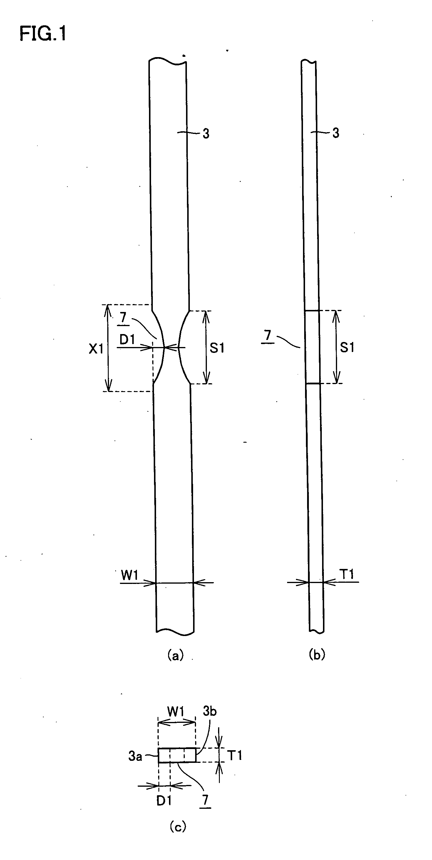
[0089]Interconnector 1 shown in FIG. 15 (a) is made for example using an electrically conductive member (copper wire) that is solder-plated for example, and has a maximum width W1 (see FIG. 1 (a)) of 2.5 mm and a maximum thickness T1 (see FIG. 1 (c)) of 0.20 mm. As a material for the conductive member, any of other materials such as an alloy of copper-aluminum-copper or copper-Inver-copper may be u...

second embodiment

[0105]An interconnector according to a second embodiment of the present invention will be described with reference to FIG. 16. FIG. 16 (a) is a plan view showing the interconnector according to the second embodiment of the present invention, FIG. 16 (b) and (c) are diagrams illustrating arrangement of electrodes on a light-receiving surface and a rear surface of solar cells, and FIG. 16 (d) is a diagram illustrating the state where the interconnector shown in FIG. 16 (a) is connected to light-receiving surface electrodes and rear electrodes of the solar cells shown in FIG. 16 (b) and (c).

[0106]Interconnector 1 shown in FIG. 16 (a) is made for example using an electrically conductive member 3 such as copper wire that is solder-plated for example, and has a maximum width W1 (see FIG. 1 (a)) of 2.5 mm and a maximum thickness T1 (see FIG. 1 (c)) of 0.20 mm. As a material for the conductive member, any of other materials such as an alloy of copper-aluminum-copper or copper-Inver-copper m...

third embodiment

[0117]An interconnector according to a third embodiment of the present invention will be described with reference to FIG. 17. FIG. 17 (a) is a plan view showing the interconnector according to the third embodiment of the present invention, FIG. 17 (b) and (c) are diagrams illustrating arrangement of electrodes on a light-receiving surface and a rear surface of solar cells, and FIG. 17 (d) is a diagram illustrating the state where the interconnector shown in FIG. 17 (a) is connected to light-receiving surface electrodes and rear electrodes of the solar cells shown in FIG. 17 (b) and (c).

[0118]Interconnector 1 shown in FIG. 17 (a) is made for example using an electrically conductive member (copper wire) 3 that is solder-plated for example, and has a maximum width W1 (see FIG. 1 (a)) of 2.5 mm and a maximum thickness T1 (see FIG. 1 (c)) of 0.20 mm. In the present embodiment as well, as a material for the conductive member, any of other materials such as an alloy of copper-aluminum-copp...


PUM

PropertyMeasurementUnit
Electrical conductivityaaaaaaaaaa
Thermal expansion coefficientaaaaaaaaaa

Abstract

An interconnector includes a strip-shaped and electrically conductive member electrically connecting respective electrodes of adjacent solar cells, the conductive member includes a plurality of planar stress relief parts and the stress relief parts are formed at equal pitches. With this structure, a stress due to a difference in thermal expansion coefficient between the interconnector and the solar cell is uniformly alleviated, so that the warp occurring to the solar cell is reduced and the reliability of the connection between the interconnector and the solar cell is improved.

Description

TECHNICAL FIELD[0001]The present invention relates to an interconnector connecting solar cells to each other, a solar cell string using the interconnector and a method of manufacturing the solar cell string, and a solar cell module using the solar cell string. More specifically, the invention relates to an interconnector with which a warp that occurs to each solar cell when the solar cells are connected by the interconnector can be reduced.BACKGROUND ART[0002]For solar cells converting solar energy directly into electrical energy, recently expectations have been remarkably growing for their availability as a next-generation energy source, particularly in terms of global environmental issues. Solar cells are classified into various kinds like the one using a compound semiconductor or the one using an organic material. Currently most solar cells use a silicon crystal. As photovoltaic power generation systems become rapidly widespread, reduction of the manufacturing cost of the solar c...

Claims


Application Information

Patent Timeline
IPC IPC(8): H01L31/048H01L31/042H01L31/18H01B5/00
CPCY02E10/50H01L31/0508
Inventor KATAYAMA, YOSHIOUMETANI, YOSHINOBUOHBASAMI, MASAHIRO
Owner SHARP KK
Why Eureka
Try Eureka