
Equipment housing with interfacing computer

Active Publication Date: 2007-03-06
T MOBILE INNOVATIONS LLC
View PDF13 Cites 39 Cited by
  • Summary
  • Abstract
  • Description
  • Claims
  • Application Information

AI Technical Summary

Problems solved by technology

One example of such information might be the malfunction of particular device within a piece of equipment.

Method used


Image

  • Equipment housing with interfacing computer
  • Equipment housing with interfacing computer
  • Equipment housing with interfacing computer

Examples


Embodiment Construction

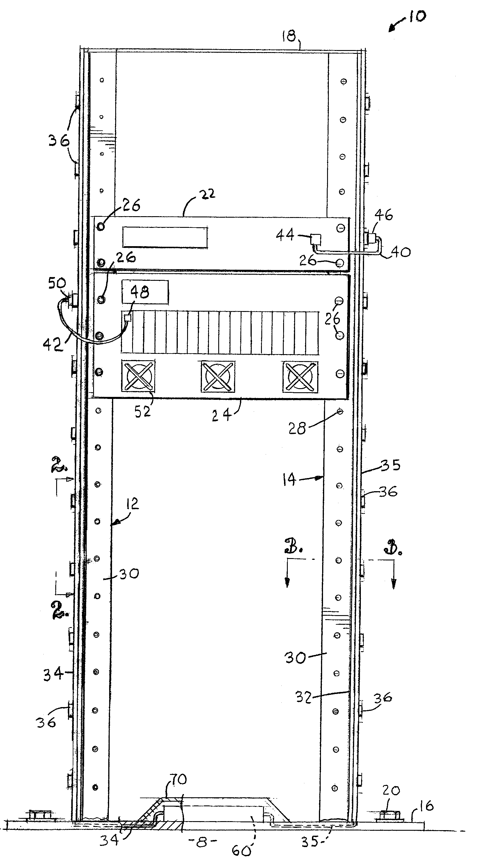
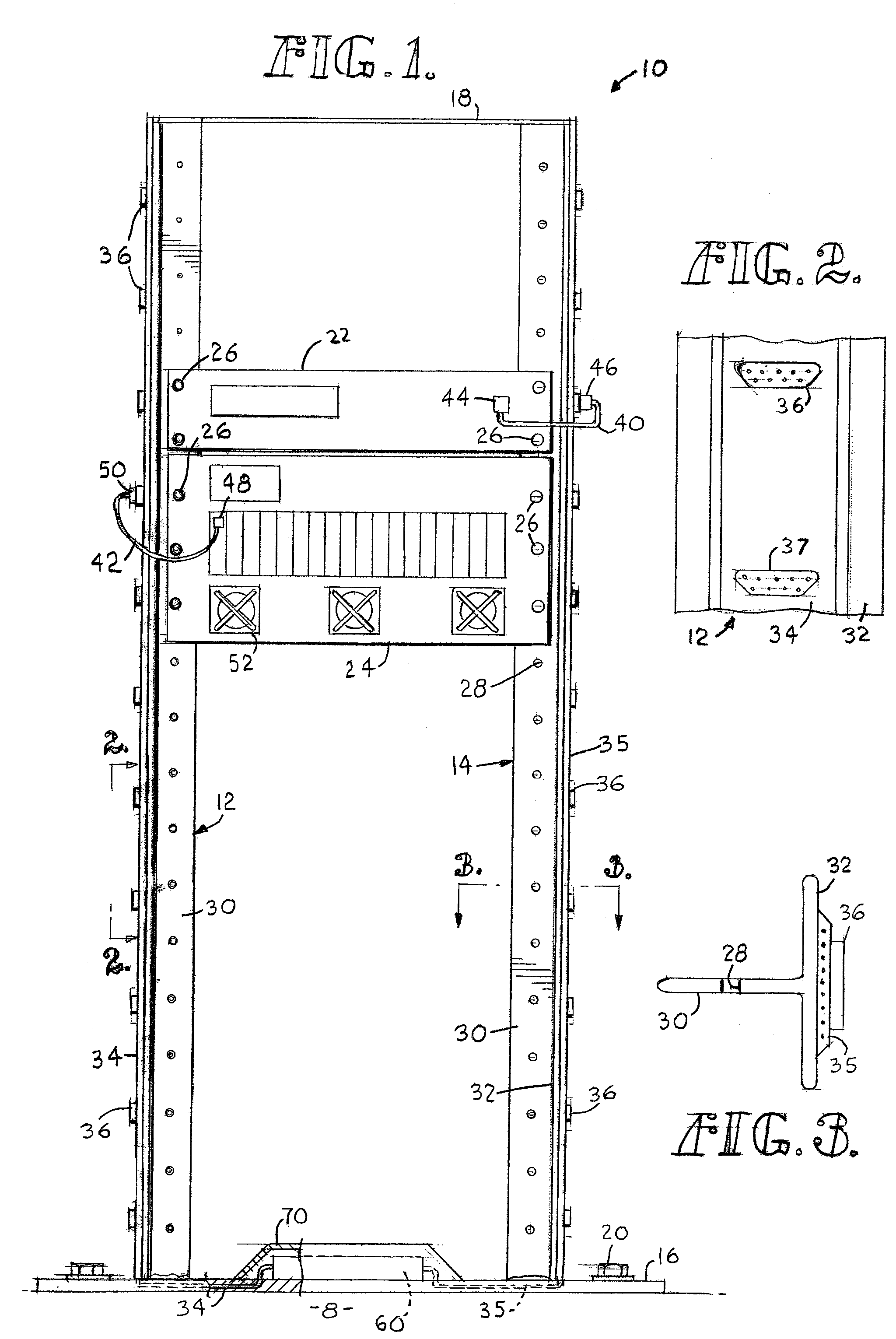
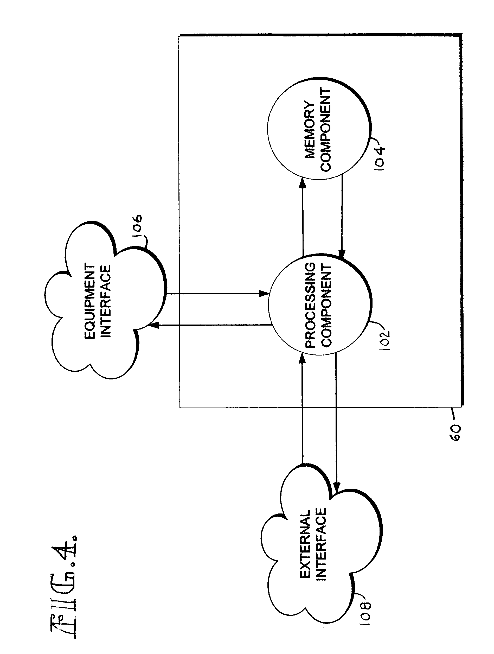
[0020]The present invention provides a system and method for housing equipment such as servers, switches, routers, and other computer or telco equipment. A special computing device is used which is associated with, and preferably physically attached to, the housing itself. This small computer is used to identify each of the components on the rack geographically and locationally within the equipment housing. It is also used to monitor anything that might malfunction in any of that housing's equipment. Preferably, the computing device will be used to automatically identify components as they are transferred in and out of the rack. This should be done in a manner such that the computing device will always have knowledge of what is installed on its particular equipment housing and also include geographic information on where that equipment housing is located. This should be possible without having to program and reprogram each individual piece of equipment as it is placed into and remov...


PUM


Abstract

An equipment housing is provided upon which heavy computing equipment, such as servers, routers, switches, and others may be mounted. A computing device is attached to the housing. The computing device is interfaced with the equipment on the housing, and also with a system that is external thereto. The disclosed housing, and others like it, may be used by an organization along with a centralized computing system such that that organization will know the exact location and status of all of its equipment at the same time and may accurately and readily monitor all of its equipment-related-assets at any given time.

Description

CROSS-REFERENCE TO RELATED APPLICATIONS[0001]Not applicable.STATEMENT REGARDING FEDERALLY SPONSORED RESEARCH OR DEVELOPMENT[0002]Not applicable.TECHNICAL FIELD[0003]This invention relates to the field of housing equipment, such as network servers, telephone switches, power supplies, and the like. More particularly, the present invention provides a new and useful method for monitoring such equipment when it is so housed.BACKGROUND OF THE INVENTION[0004]Racks for housing equipment, such as servers, switches, routers, and the like are known in the art. With these types of racks, various components are rigidly secured by fasteners. The equipment will typically have a flange on each side which receives a threaded bolt which is used to secure the flange to a reciprocating threaded receptacle on the rack. The pieces of equipment are stacked one on top of the other. For example, on a typical eight foot rack, a telephone switch may be located in the bottom-most part of the rack. A server mig...

Claims


Application Information

Patent Timeline
Patent Type & Authority Patents(United States)
IPC IPC(8): G05B23/02A47F7/00G06F1/16G06F13/00G06F15/173H05K7/00
CPCG06F1/181H05K7/1488H05K5/0252G06F13/409
Inventor SENOGLES, BRIAN LAWRENCETAYLOR, PAUL WESLEYFINK, NATHAN AARONWATKINS, RONDA LYNDELZER, JEFFREY
Owner T MOBILE INNOVATIONS LLC
Learn More