
Compressor for use in minimally invasive surgery

a compressor and minimally invasive technology, applied in the field of compressor tools for use can solve the problems of time-consuming and laborious to set up and use the tools, and the compressor tools are not usable in minimally invasive surgery

Active Publication Date: 2007-03-13
DEPUY SPINE INC (US)
View PDF16 Cites 40 Cited by
  • Summary
  • Abstract
  • Description
  • Claims
  • Application Information

AI Technical Summary

Benefits of technology

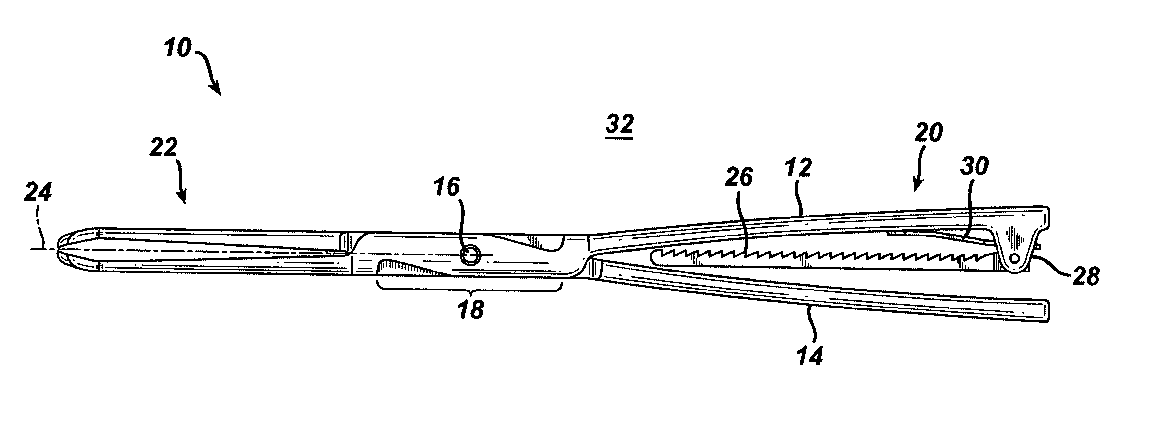
[0012]In a further embodiment, a compressor tool of the invention as described above can be configured to have a first closed position for insertion of the compressor tool through an incision or portal wherein the first and second elongate element working portions are proximate to the tool longitudinal axis, and a second working position wherein the first and second working portions are spaced apart. The tool can further be configured so that articulation of the tool between the first and second positions results in no increase in dimension of the tool in a tool pivot region including the pivot point of each elongate member.
[0013]In a more detailed embodiment, the tool can further be configured so that in the first closed position, and for the first elongate element, the handle portion extends proximally from t...

Problems solved by technology

This makes conventional compressor tools unusable in minimally invasive surgery.
Each of these designs has its own set of problems however, including the amount of time it takes to set up and use the tools, and the extra mechanical advantage that the tools provide.

Method used


Image

  • Compressor for use in minimally invasive surgery
  • Compressor for use in minimally invasive surgery
  • Compressor for use in minimally invasive surgery

Examples


Embodiment Construction

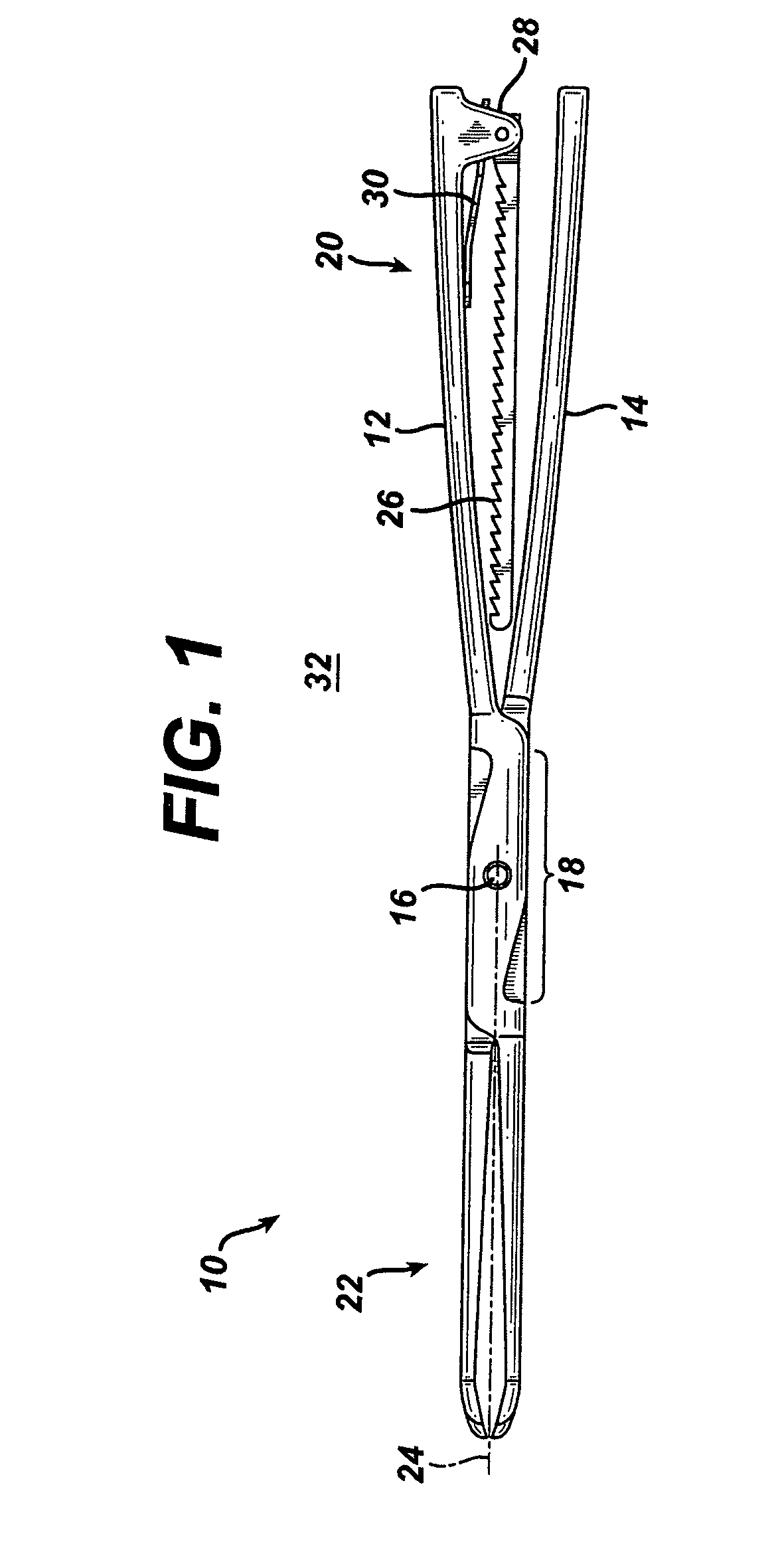
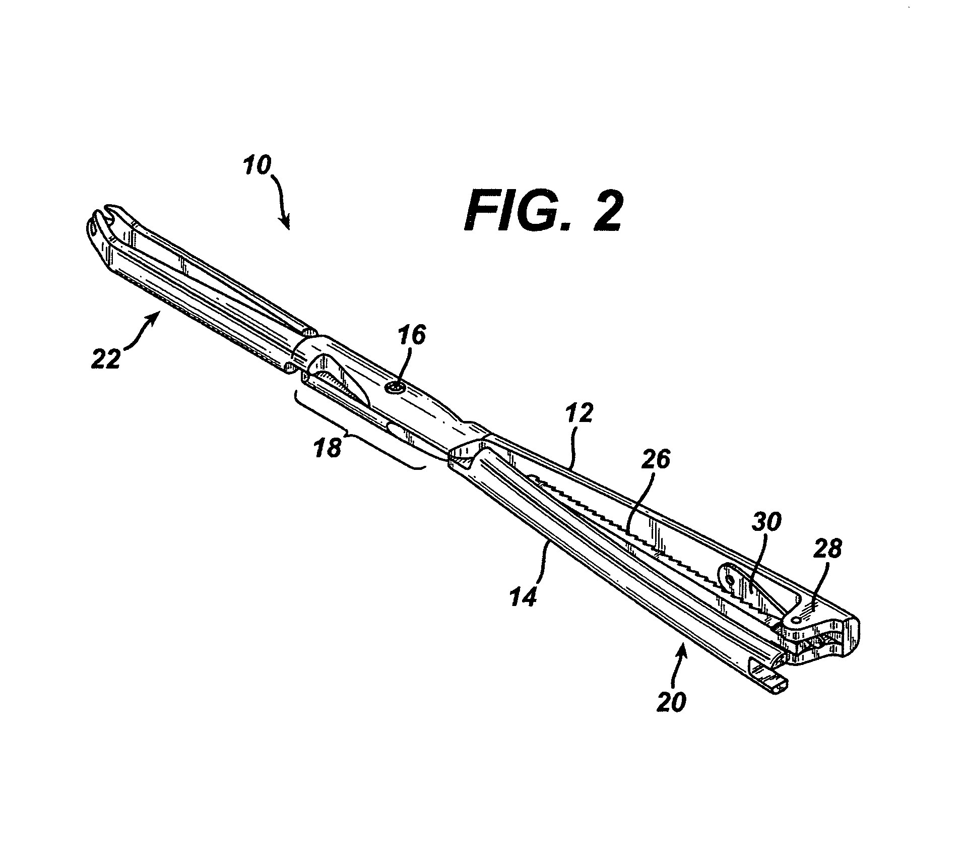
[0020]The present invention provides a compression tool providing the benefits of known compression tools for use in spinal fixation surgery, but also having a smaller profile, especially in a pivot region of the tool, so that the tool may be effectively used in minimally invasive surgery. Another feature of at least one embodiment of the invention is that the pivot region of the compression tool maintains its cross-sectional dimensions as the tool is articulated between open and working positions so that in use, the tool may be placed for operation so that the pivot region is located within the incision or portal used for the surgery and may be operated without constraints arising from the dimensions of the incision or portal.

[0021]As illustrated in side and perspective views in FIGS. 1 and 2, respectively, a compressor tool 10 of the invention comprises first 12 and second 14 elongate members rotatably connected at pivot point 16. Tool 10, having a tool longitudinal axis 24, can b...


PUM


Abstract

A compressor tool for use in minimally invasive surgery is provided having first and second elongate elements where each elongate element is connected to the other at a pivot point within a pivot region of each element for rotating articulation in an articulation plane with respect to each other. The first and second elongate elements are configured to provide a tool pivot region including the pivot point, a tool handle proximal to the tool pivot region, and a tool working portion distal to the too pivot region so that pressure applied to the tool handle portion results in a compressive force being applied by the tool working portion. The tool has a first closed position for insertion of the tool through an incision or portal so that the pivot region is located within the incision or portal, and a second working position where the tool working portion is arranged to provide a compressive force to spaced apart elements within a patient's body. Articulation of the tool between the first closed position and the second working position results in no increase in dimension of the tool in the pivot region.

Description

RELATED APPLICATIONS[0001]This application claims priority to provisional application U.S. Ser. No. 60 / 400,966, filed Aug. 2, 2002.FIELD OF THE INVENTION[0002]The present invention relates to devices and systems for compressing a patient's spine between fixation screws in a spinal fixation construct. More particularly, the invention provides a compressor tool for use in minimally invasive surgery having a small cross section and a pivot region that remains smaller than the minimally invasive surgery entry site regardless of the state of the compressor tool.BACKGROUND OF THE INVENTION[0003]The use of spinal fixation instrumentation to align and / or fix a desired relationship between adjacent vertebral bodies is well established. Such instrumentation typically includes a spinal fixation element, such as a relatively rigid fixation rod, that is coupled to adjacent vertebrae by attaching the element to screws which have been inserted into the patient's vertebrae or to spinal hooks which ...

Claims


Application Information

Patent Timeline
IPC IPC(8): A61B17/58A61B17/00A61B17/02A61B17/28A61B17/70A61B17/88
CPCA61B17/025A61B17/2812A61B17/2816A61B17/7079A61B2017/2919A61B2017/0256A61B17/7032
Inventor NEWTON, PETERGRACIA, MARKVARIEUR, MICHAEL S.BREECH, CARRIE A.
Owner DEPUY SPINE INC (US)
Learn More