

Method for resizing and moving an object on a computer screen
- Summary
- Abstract
- Description
- Claims
- Application Information
AI Technical Summary
Benefits of technology
Problems solved by technology
Method used
Image

Examples
Embodiment Construction
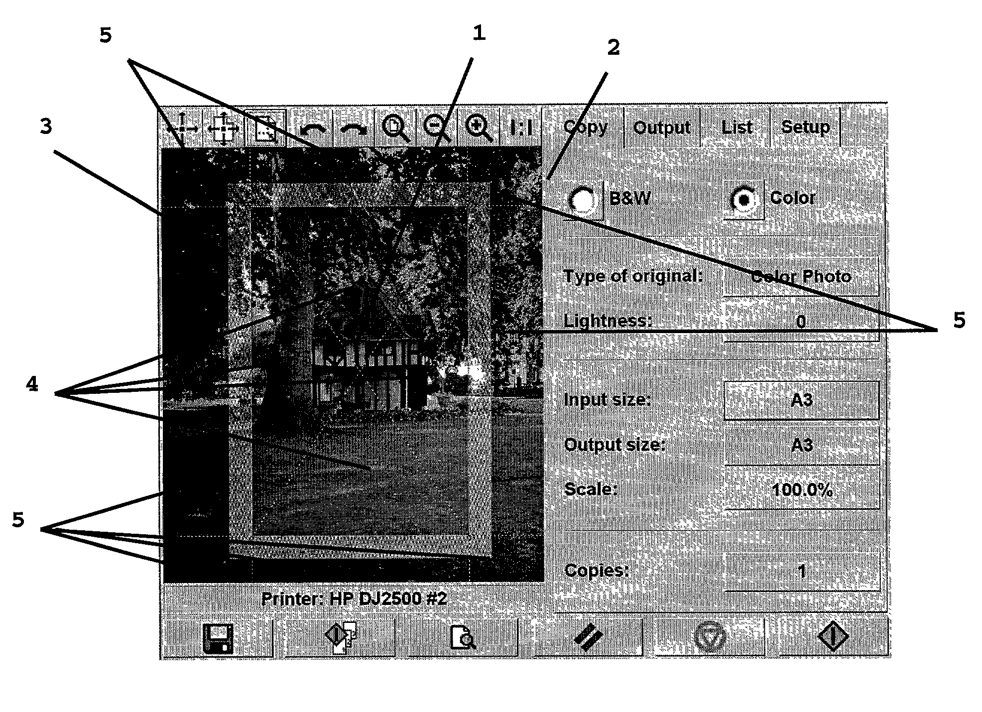
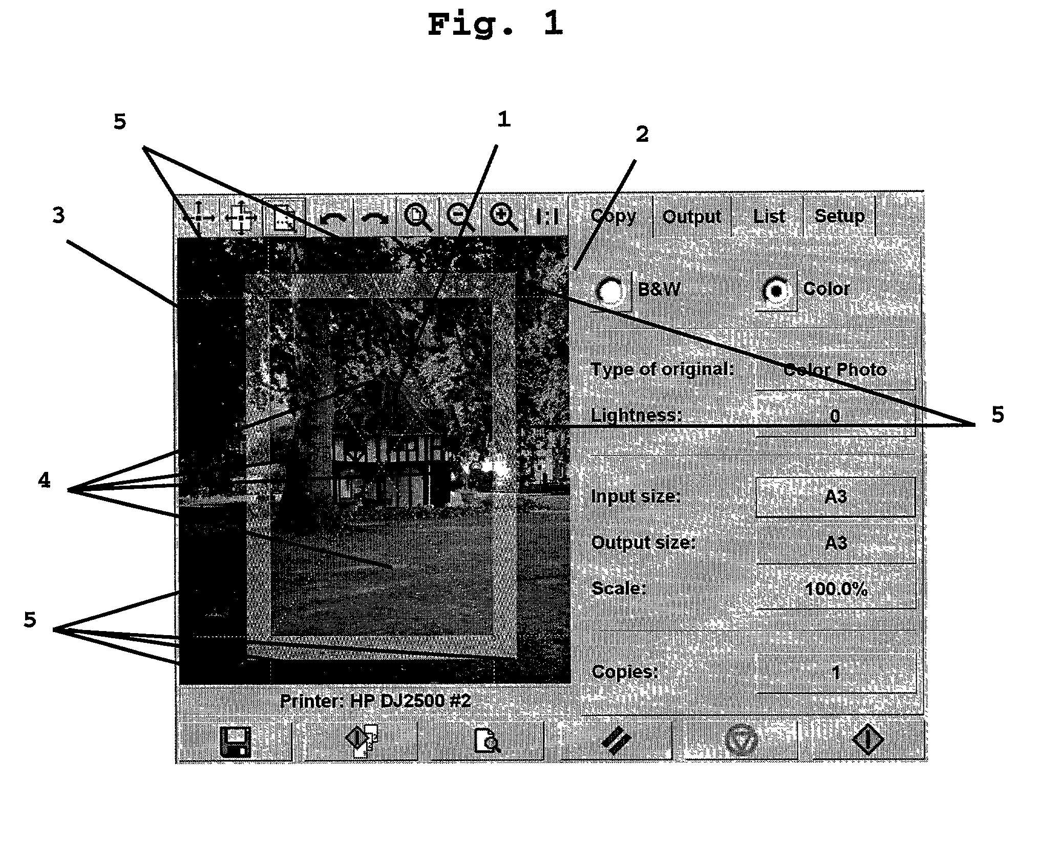
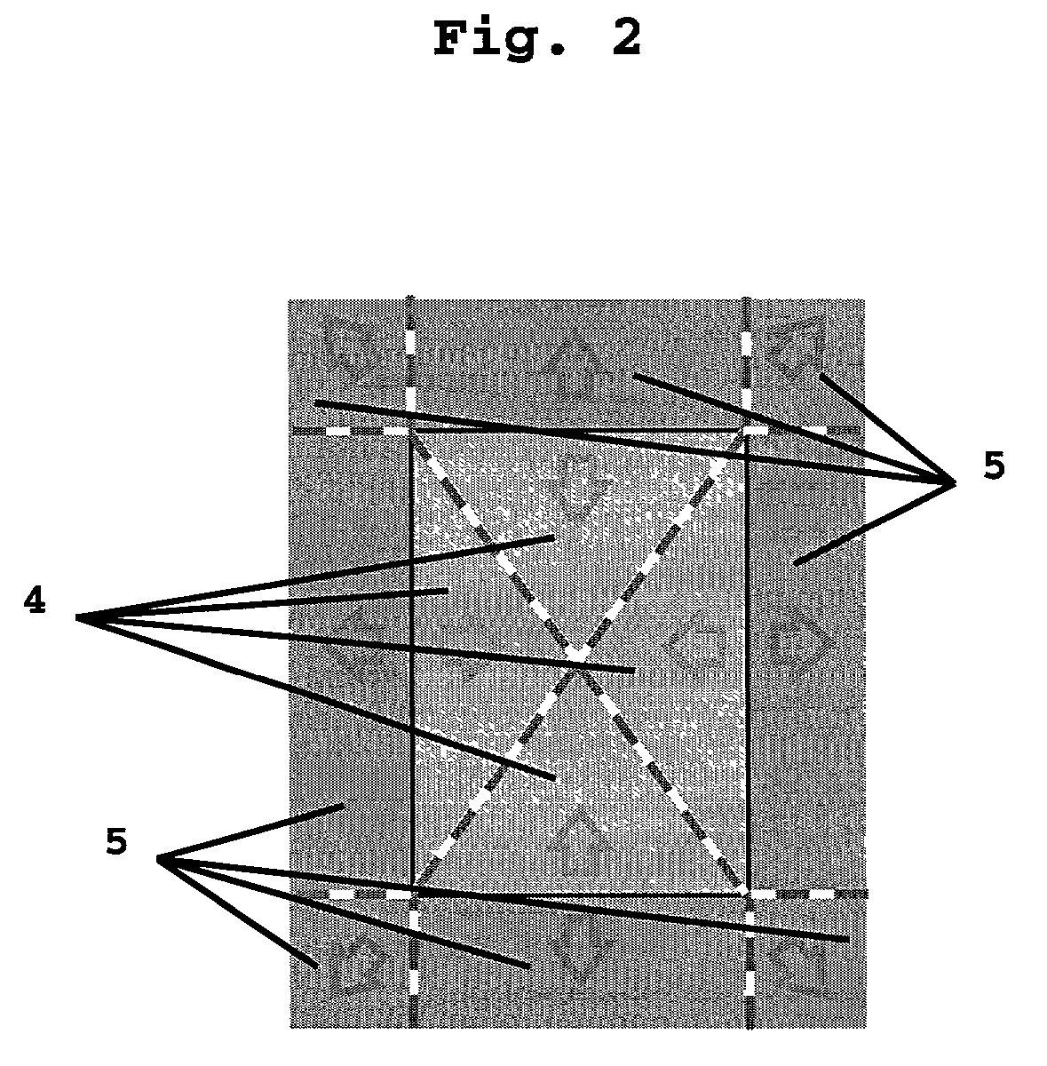
[0004]It is an object of the present invention to overcome the above described disadvantage of the known user interfaces by providing a method for defining the size of an object displayed on a computer screen, the computer screen having a matrix of sensor points, said method comprising the steps of:[0005]displaying an object on a computer screen,[0006]defining at least one screen area having a reference point associated therewith,[0007]reading an input from a sensor point in a screen area,[0008]calculating a vector between the read input and the reference point of that screen area, and[0009]defining the size of the object based on that vector.
[0010]The object which is going to be resized may as an example be a picture or picture frame, text or a text frame or any other object being visualized on a computer screen. The computer screen may be a regular computer screen, even though the following description focuses on a touch screen. The computer screen may also be a window on a comput...
PUM
 Abstract
Description
Claims
Application Information