Vibration meter and method of measuring a viscosity of a fluid

a technology of vibration meter and fluid, which is applied in the direction of liquid/fluent solid measurement, direct mass flowmeter, instruments, etc., can solve the problem of limiting the use of such vibration meters for and affecting the accuracy of mass flow rate measuremen

Inactive Publication Date: 2007-03-20
ENDRESS HAUSER FLOWTEC AG
View PDF29 Cites 11 Cited by
  • Summary
  • Abstract
  • Description
  • Claims
  • Application Information

AI Technical Summary

Benefits of technology

[0091]One advantage of the invention is that it can be implemented using conventional flexural mode Coriolis mass flow / density sensors of the kind described without having to make any changes to the mechanical design of such sensors. Thus, the method of the invention can also be implemented in Coriolis mass flowmeter-densimeters that are already in use.
is that it can be implemented using conventional flexural mode Coriolis mass flow / density sensors of the kind described without having to make any changes to the mechanical design of such sensors. Thus, the method of the invention can also be implemented in Coriolis mass flowmeter-densimeters that are already in use.

Problems solved by technology

The torsional vibrations performed by the flow tube cause shearing forces in the fluid, which, in turn, have a damping effect on the torsional vibrations.
While WO-A 95 / 16897 describes that radial mode vibration meters can be used to measure both the mass flow rate and the viscosity of fluids, the use of such vibration meters for mass flow rate measurements has so far been limited nearly exclusively to gaseous fluids.
It has turned out that the damping effect of viscosity, particularly on the amplitude of the above-mentioned, preferably mass-flow-rate-dependent second vibration mode, is so high that even at viscosities that are just slightly above that of water, this second vibration mode is practically no longer detectable with sensors.
It has turned out that the viscosities hitherto determined in such Coriolis mass flow meters by measuring solely the excitation current practically only for the purpose of compensating the primary measured values, namely a mass flow rate value and a density value, are too inaccurate to be suitable for output as additional viscosity values.

Method used


Image

  • Vibration meter and method of measuring a viscosity of a fluid
  • Vibration meter and method of measuring a viscosity of a fluid
  • Vibration meter and method of measuring a viscosity of a fluid

Examples


Embodiment Construction

[0099]While the invention is susceptible to various modifications and alternative forms, exemplary embodiments thereof have been shown by way of example in the drawings and will herein be described in detail. It should be understood, however, that there is no intent to limit the invention to the particular forms disclosed, but on the contrary, the intention is to cover all modifications, equivalents, and alternatives falling within the spirit and scope of the invention as defined by the intended claims.

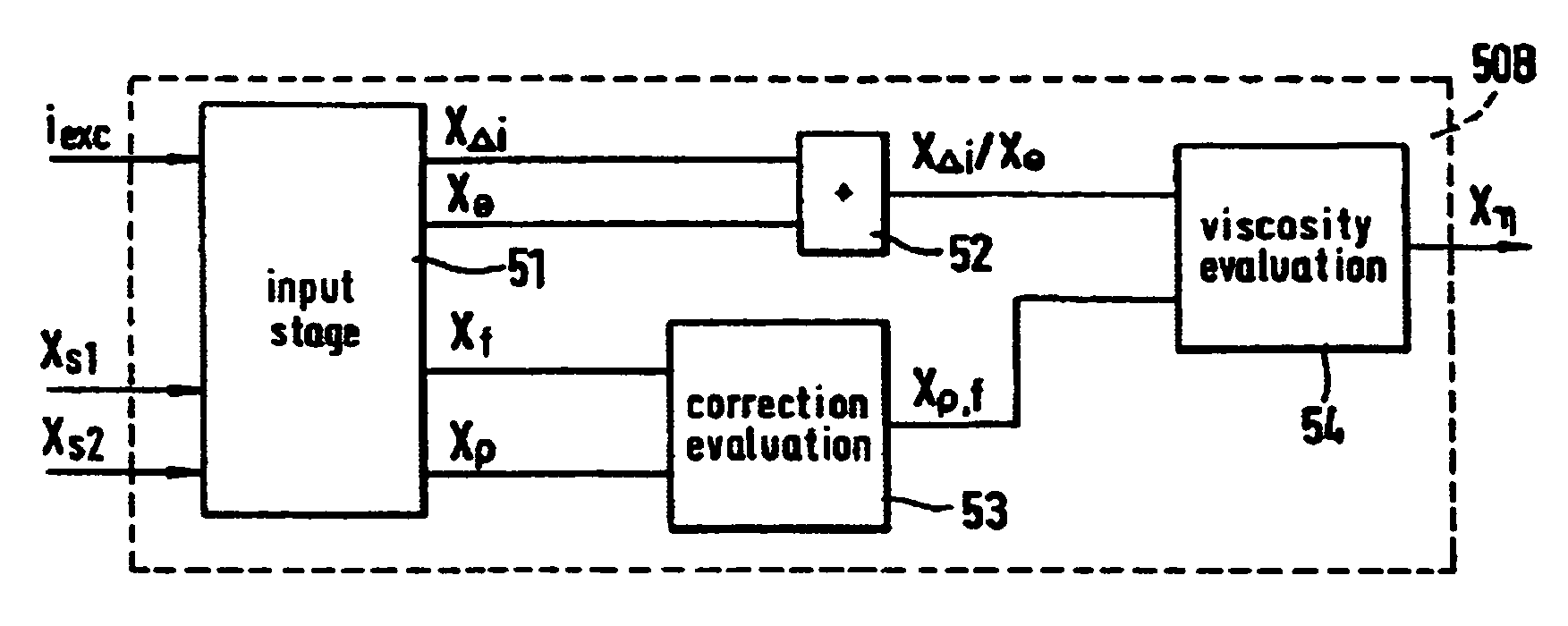
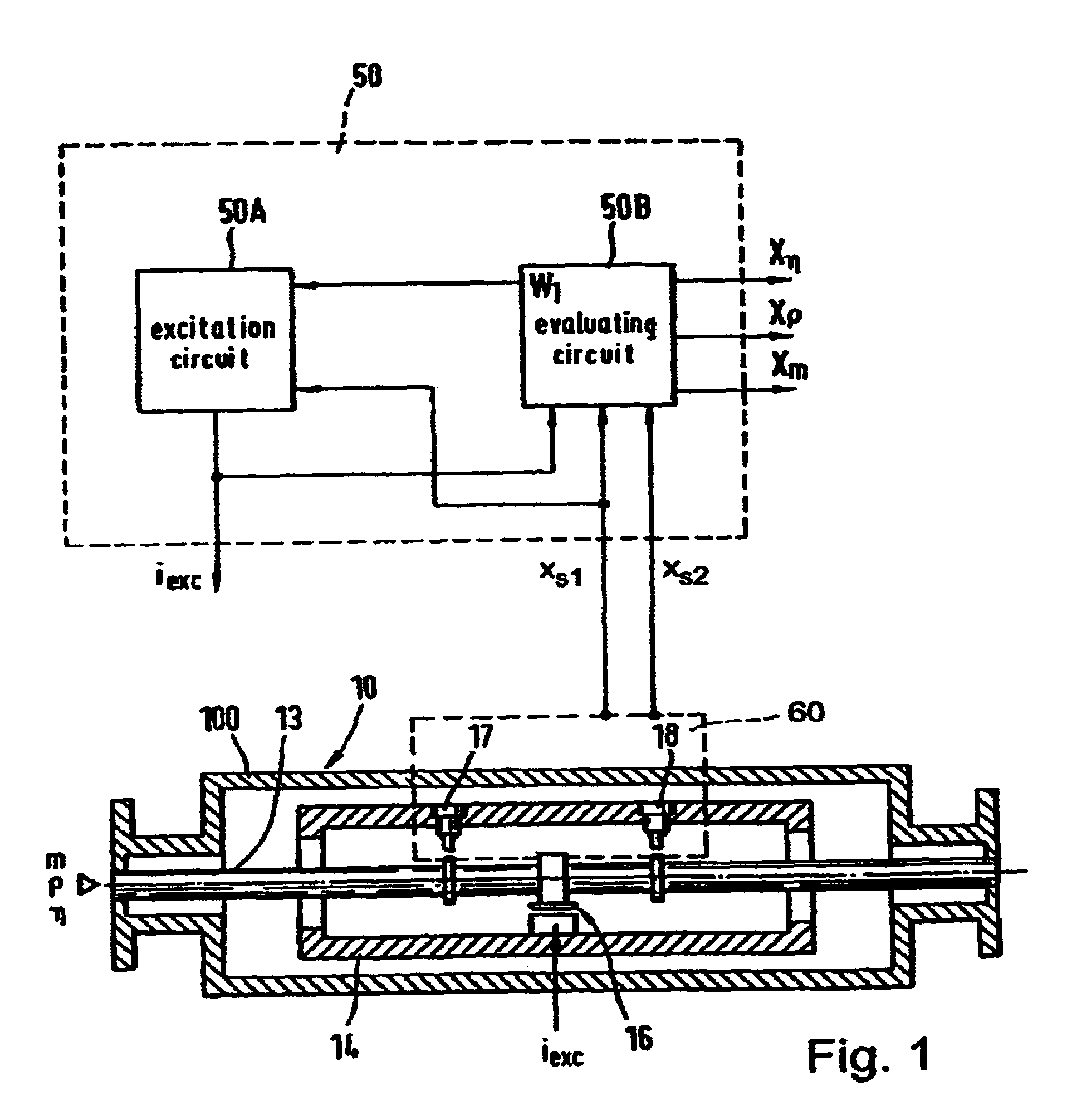
[0100]FIG. 1 shows schematically a vibration meter that serves to sense a viscosity η of a fluid flowing through a pipe (not shown) and to map it into a viscosity value Xη representative of the viscosity η of the fluid.

[0101]Furthermore, the vibration meter, besides determining the viscosity η, preferably serves to determine a density ρ and a mass flow rate m of the fluid, particularly simultaneously, and to convert them in a corresponding manner into a density value Xρ, representing ...


PUM

PropertyMeasurementUnit
natural frequencyaaaaaaaaaa
diametersaaaaaaaaaa
viscosityaaaaaaaaaa

Abstract

A vibration meter and a method of measuring a viscosity of a fluid flowing through a pipe are disclosed. The vibration meter comprises meter electronics and a transducer assembly with an electromechanical excitation arrangement and with a flow tube which oscillates in operation. A sensor arrangement produces sensor signals representative of inlet-side and outlet-side deflections of the flow tube. An evaluation circuit derives from said sensor signals and from an excitation current generated by an excitation circuit for the excitation arrangement a viscosity value representative of the viscosity of the fluid.

Description

RELATED APPLICATIONS[0001]This application is a continuation of U.S. patent application Ser. No. 09 / 844,013, filed Apr. 27, 2001 now U.S. Pat. No. 6,651,513, which claims the benefit of U.S. Provisional Application No. 60 / 221,622, filed Jul. 28, 2000, and claims priority to German Application No. 100 20 606.9, filed Apr. 27, 2000, and European Patent Office Application No. 00110086.6.FIELD OF THE INVENTION[0002]This invention relates to a method of measuring a viscosity of a fluid flowing through a pipe, and to a vibration meter for carrying out this method. Furthermore, the invention relates to the use of a flexural mode Coriolis mass flowmeter-densimeter for measuring the viscosity of the fluid.BACKGROUND OF THE INVENTION[0003]Coriolis mass flowmeter-densimeters are preferably used for measuring a mass flow rate and / or a density of a fluid flowing through a pipe with a high degree of accuracy.[0004]A flexural mode Coriolis mass flowmeter-densimeter, as is well known, is a vibratio...

Claims


Application Information

Patent Timeline
Patent Type & Authority Patents(United States)
IPC IPC(8): G01N11/10G01F1/84G01N9/00
CPCG01F1/8409G01F1/8413G01F1/8418G01N11/16G01F1/8436G01F1/849G01N9/002G01F1/8422
Inventor WENGER, ALFREDFUCHS, MICHAELMATT, CHRISTIANDRAHM, WOLFGANG
Owner ENDRESS HAUSER FLOWTEC AG
Why Eureka
Try Eureka