Method and apparatus for control of exposure in radiological imaging systems

Inactive Publication Date: 2007-03-20
GE MEDICAL SYSTEMS INC
View PDF16 Cites 7 Cited by
  • Summary
  • Abstract
  • Description
  • Claims
  • Application Information

AI Technical Summary

Benefits of technology

[0010]An embodiment of the present invention is an apparatus and method

Problems solved by technology

Now, this method can present problems.

Method used


Image

  • Method and apparatus for control of exposure in radiological imaging systems
  • Method and apparatus for control of exposure in radiological imaging systems
  • Method and apparatus for control of exposure in radiological imaging systems

Examples


Embodiment Construction

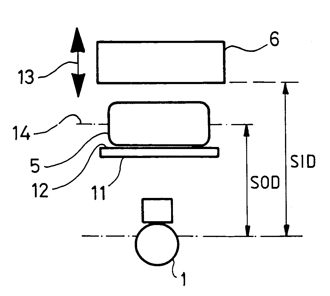
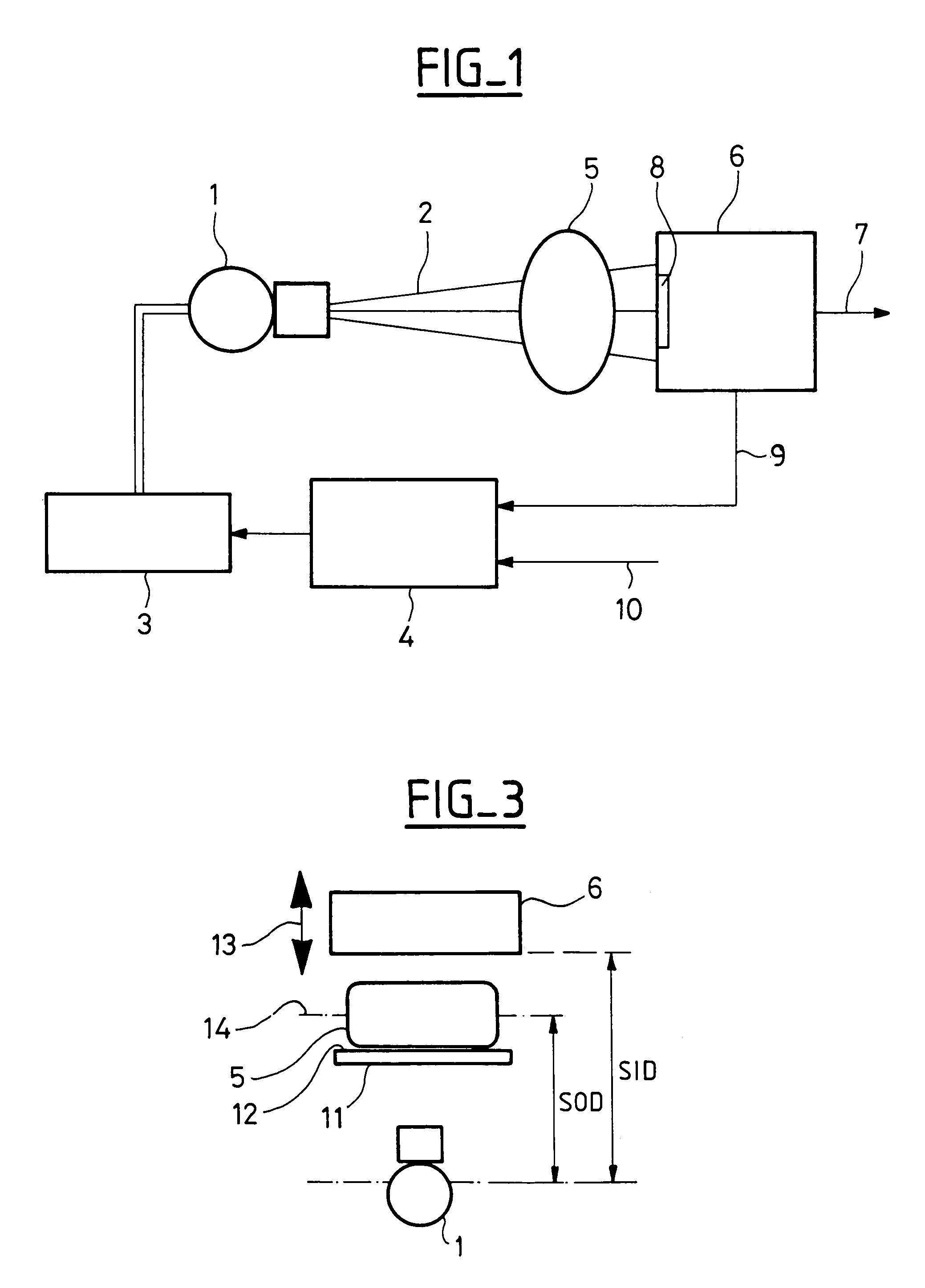
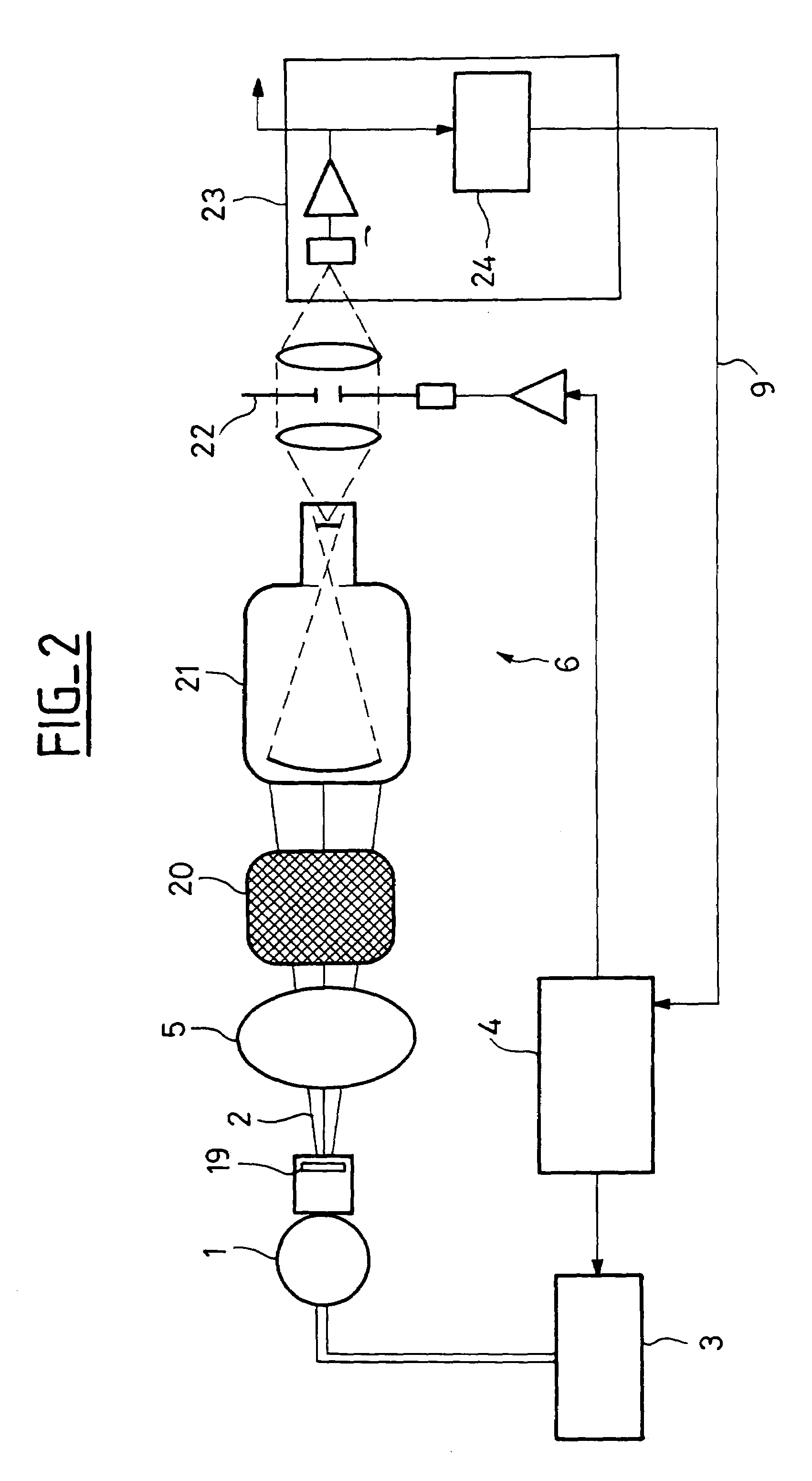
[0016]As can be seen in FIG. 1, the radiology apparatus comprises an X-ray tube 1 capable of emitting an X-ray beam 2 having an axis of propagation 16. The X-ray tube 1 is supplied by a high-voltage source 3 controlled by a control unit 4. Placed on the path of the X-ray beam 2 are an object 5 having to be studied, for example, a part of a object's body, and a digital type image receptor 6, for example, a solid-state receptor, capable of emitting on output on a line 7 a digital signal representing the image obtained by the image receptor 6, which picks up the X-ray beam after it has crossed the object 5. The line 7 can be connected to image processing means and to display means, such as a screen, not represented.

[0017]The radiology apparatus also includes a brightness sensor 8 capable of emitting on the line 9 connected to the control unit 4 a signal representing the brightness of the image obtained. The brightness sensor can be formed by a part of the solid-state detector. The cont...


PUM


Abstract

Method and apparatus for adjustment of the entrance dose of a radiology apparatus of the type containing a means of X-ray beam emission, a means of detection of the X-ray beam after it has crossed an object having to be visualized, and a means of visualization connected to the means of detection, in which the distance between the means of emission and the object is estimated and, when the distance between the means of emission and the object or the distance between the means of emission and the means of detection varies, the entrance dose is modified according to said distances in order to maintain an appreciably constant equivalent dose in the plane containing the object, the distance between the means of emission and the means of detection being known.

Description

CROSS-REFERENCE TO RELATED APPLICATIONS[0001]This application claims the benefit of a priority under 35 USC 119(a)-(d) to French Patent Application No. 99 02711 filed Mar. 4, 1999, the entire contents of which are hereby incorporated by reference.BACKGROUND OF THE INVENTION[0002]The present invention concerns the field of radiological imaging. An object such as a human being or an animal or an object if a human being or animal to be studied under X-rays is placed between an X-ray source and a means of detection making possible a visualization of the X-ray beam after it crosses the object.[0003]The control of radiological image exposure usually comprises keeping the brightness of the visible images constant. This principle is derived from the first constant sensitivity image receptors, notably, radiographic films for static images and fluorescent screens for fluoroscopy.[0004]The known systems using indirect image receptors, based, for example, on image intensifiers, reproduce that b...

Claims


Application Information

Patent Timeline
IPC IPC(8): H05G1/44H05G1/36A61B6/00A61B6/04G01T1/166
CPCG01T1/166
Inventor BOUTENKO, VLADISLAVKLAUSZ, REMY
Owner GE MEDICAL SYSTEMS INC
Why Eureka
Try Eureka