Drill template with integral vacuum attach

a vacuum attaching and drill template technology, applied in the direction of turning machine accessories, manufacturing tools, transportation and packaging, etc., can solve the problems of high ergonomic injury rate of drill operators in one manufacturing environment, increased operator exposure to injury, and unhealthy absorbing of fine particles in the human body

Inactive Publication Date: 2007-03-27
THE BOEING CO
View PDF13 Cites 49 Cited by
  • Summary
  • Abstract
  • Description
  • Claims
  • Application Information

AI Technical Summary

Problems solved by technology

Drill operators in one manufacturing environment have experienced a high rate of ergonomic injuries—such as carpal tunnel syndrome—some of which occur, for example, due to the number of manually drilled holes and the drilling equipment used.
Due to the nature of the structure and the capabilities of the tools used, the manual drilling operation for a structure of composite skins over aluminum substructure typically consists of at least four drilling passes, increasing operator exposure to injury with each additional pass.
The fine particles are unhealthy when absorbed in the human body.
Also, the dust of fine particles may contaminate sensitive equipment and cause reliability problems.
The separate operation of these systems is generally inefficient for collection of dust particles generated during the drilling process, and the separate operation of these systems further increases operator exposure to a high rate of ergonomic injuries when manually drilling a large number of holes.
Thus, the prior art templates are not made to fit exactly to the mold line surface of the structure, and are generally copied from a master tool, rather than directly from the mold line specifications.
The lack of exact of fit to the mold line generally limits the positioning and drilling accuracy of the template.

Method used


Image

  • Drill template with integral vacuum attach
  • Drill template with integral vacuum attach
  • Drill template with integral vacuum attach

Examples


Embodiment Construction

[0023]The following detailed description is of the best currently contemplated mode of carrying out the invention. The description is not to be taken in a limiting sense, but is made merely for the purpose of illustrating the general principles of the invention, since the scope of the invention is best defined by the appended claims.

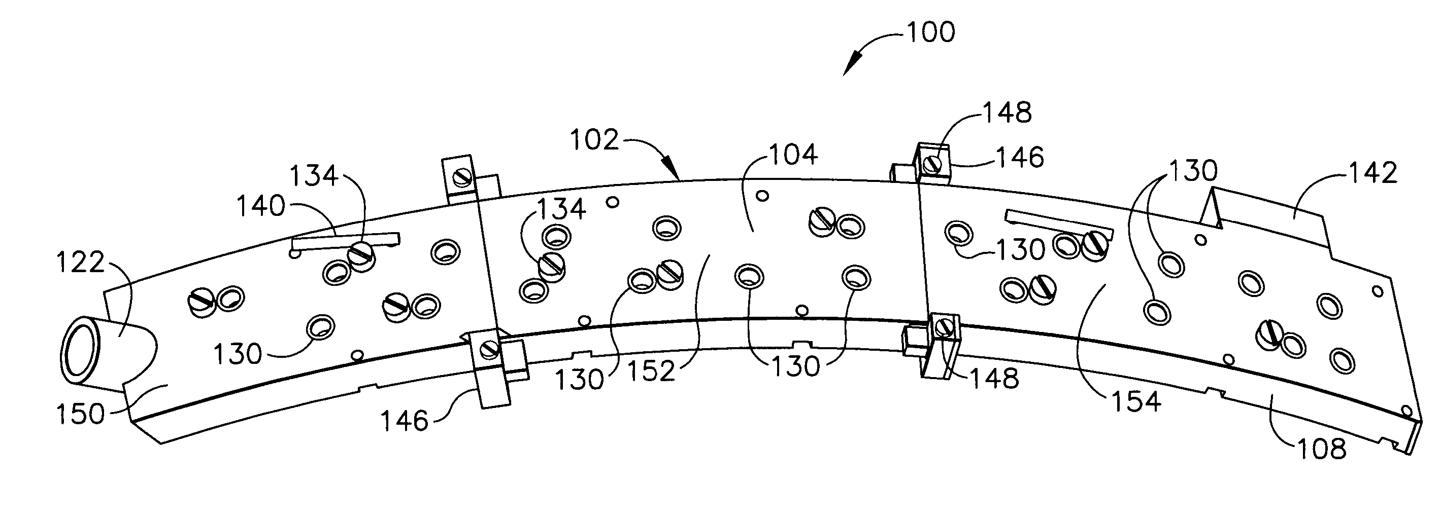
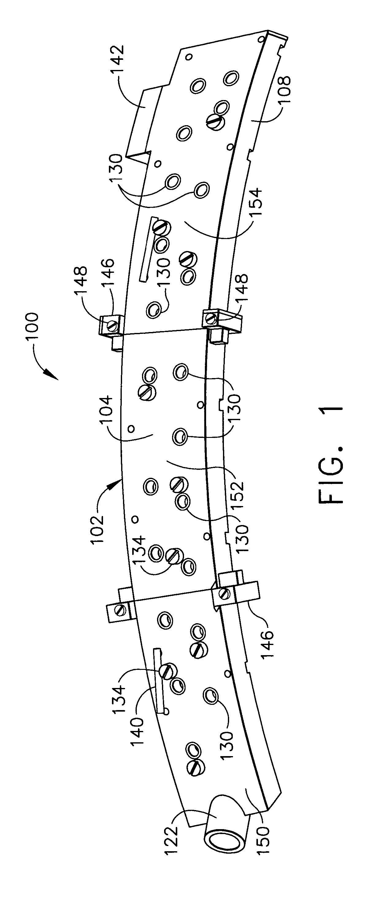
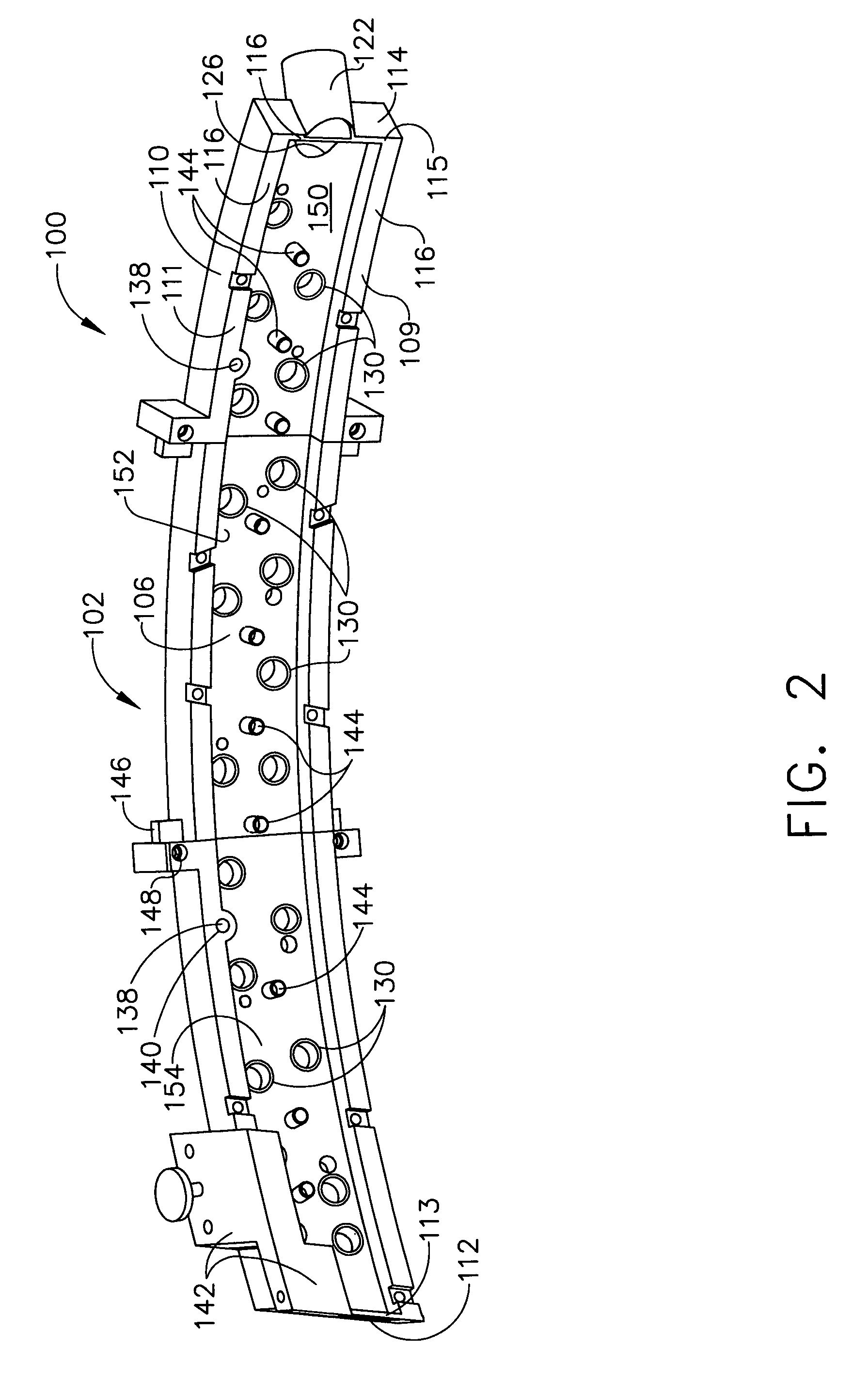
[0024]Broadly, one embodiment of the present invention provides a template for drilling a pattern of holes in a structure and for collecting debris generated by the drilling process. The structure may be part of a product manufactured in the aerospace, marine, or refrigeration industries as typified by, for example, a skin portion attached to a frame substructure. Drill templates are generally useful in such situations for drilling holes in precise locations through the skin and into or through a portion of the frame, for example, for attaching the skin to the frame with fasteners received by the holes. The skin or structure may have a precisely defined ...


PUM

PropertyMeasurementUnit
diameteraaaaaaaaaa
diameteraaaaaaaaaa
diameteraaaaaaaaaa

Abstract

A drill template includes a vacuum housing with a skirt having a CAD-formed contact surface formed to an exact fit with a mold line surface of a structure. The drill template includes at least one drill guide bushing extending through the vacuum housing from a top surface to an interior surface of the vacuum housing; a vacuum port integral to the vacuum housing; and at least one index hole for positioning and aligning the vacuum housing on the structure. Index holes extend from the top surface through to the CAD-formed contact surface of the vacuum housing. A CAD-formed edge of part locator is formed according to a CAD solid model of the aircraft fuselage and fits to a precise location of the structure for precisely positioning the template on the structure. A vacuum port provides vacuum to the interior of the vacuum housing for removing drilling debris and dust.

Description

BACKGROUND OF THE INVENTION[0001]The present invention generally relates to manufacture and assembly of structures using composite materials and, more particularly, to drilling holes at precise locations in a part—such as a composite or metallic aircraft part—and, for safety and health reasons, collecting the debris—such as composite dust or metallic drill chips—generated by the drilling process.[0002]In conventional practice, before a pattern of holes is drilled in a part to be assembled into a structure, a template, or jig, is made and placed on the surface of the part to be drilled. For example, in the aerospace industry, the structure, or assembly, may be a composite aircraft skin over an aluminum substructure. Examples may also be found in the marine and refrigeration industries, such as applications to boat hulls and heating / air conditioning ducts. The template or jig contains holes conforming to the desired hole pattern that is to be made on the surface of the part to be dril...

Claims


Application Information

Patent Timeline
Patent Type & Authority Patents(United States)
IPC IPC(8): B23B47/28B23B47/34B23Q11/00
CPCB23B47/287B23B35/00B23Q11/0046B23B2215/04B23B2226/27B23B2260/118B23B2270/62Y10T408/554B23B47/28Y10T408/567Y10T408/50Y10T408/03B33Y80/00
Inventor DODS, BRYAN G.MACKE, JOHNMORRISONSCOTT, ROBERT W.
Owner THE BOEING CO
Why Eureka
Try Eureka