DC power source unit with battery charging function

a technology of dc power source unit and function, which is applied in the direction of process and machine control, safety/protection circuit, instruments, etc., can solve the problem of shortening the service life of the switch

Inactive Publication Date: 2007-03-27
KOKI HLDG CO LTD
View PDF10 Cites 788 Cited by
  • Summary
  • Abstract
  • Description
  • Claims
  • Application Information

AI Technical Summary

Benefits of technology

[0008]In view of the foregoing, it is an object of the present invention to provide a DC power source unit having a battery charging function in which a rush current is prevented from being flowed in a switching device connected between a switching power source and the battery.

Problems solved by technology

However, whenever the battery runs low, the battery pack needs to be removed and charged or else replaced with another battery pack that has already been charged.
However, this situation has a problem in that the operator of the cordless power tool must carry both the DC power source unit and the battery pack's charging unit to the work area.
However, there arises a problem such that the battery to be charged by the DC power source unit has a rated voltage that is not the same as the voltage applied to the power tool.
The rush current shortens the service life of the switch.

Method used


Image

  • DC power source unit with battery charging function
  • DC power source unit with battery charging function
  • DC power source unit with battery charging function

Examples


Embodiment Construction

[0019]A direct current (DC) power source unit according to an embodiment of the present invention will be described while referring to the accompanying drawings.

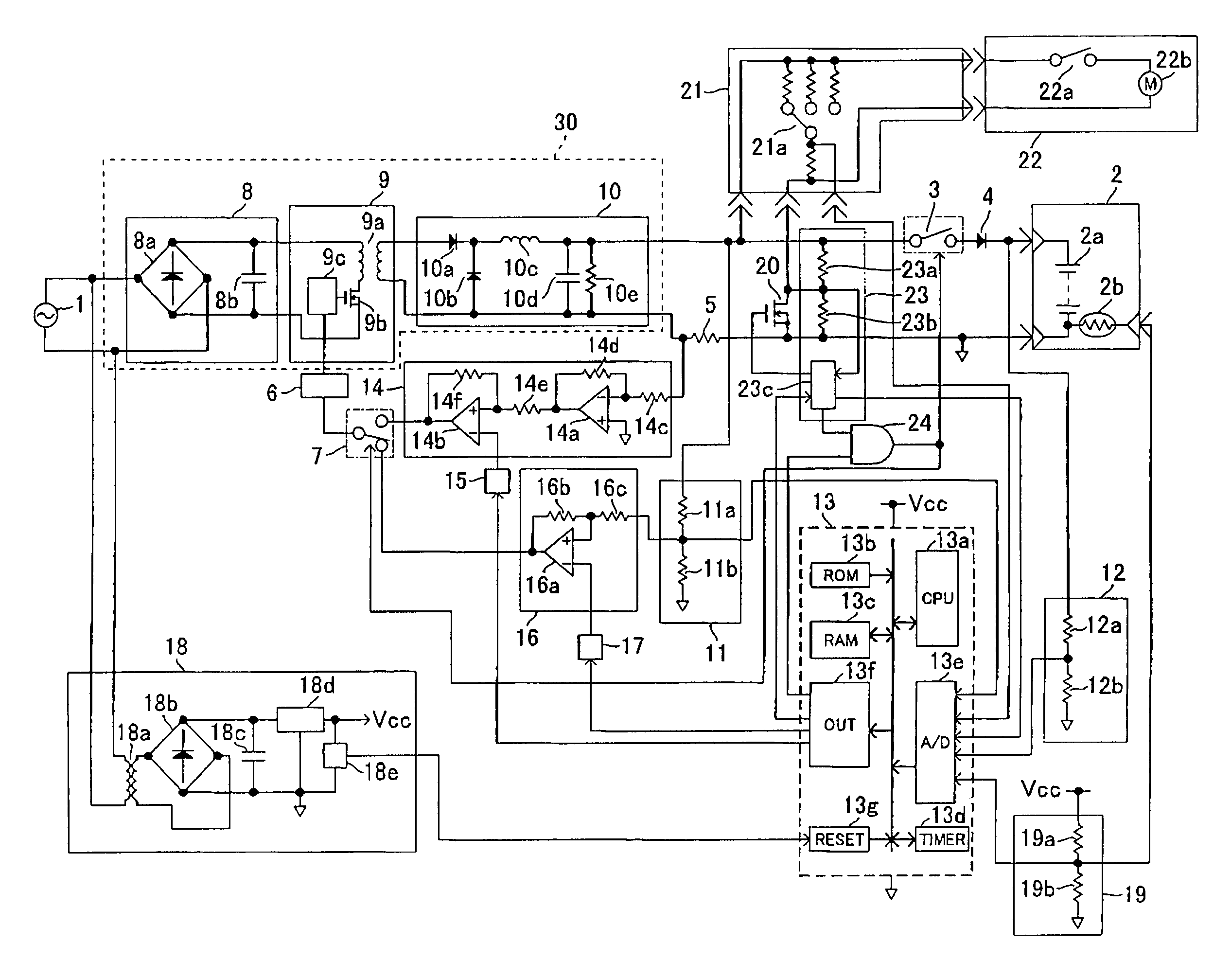
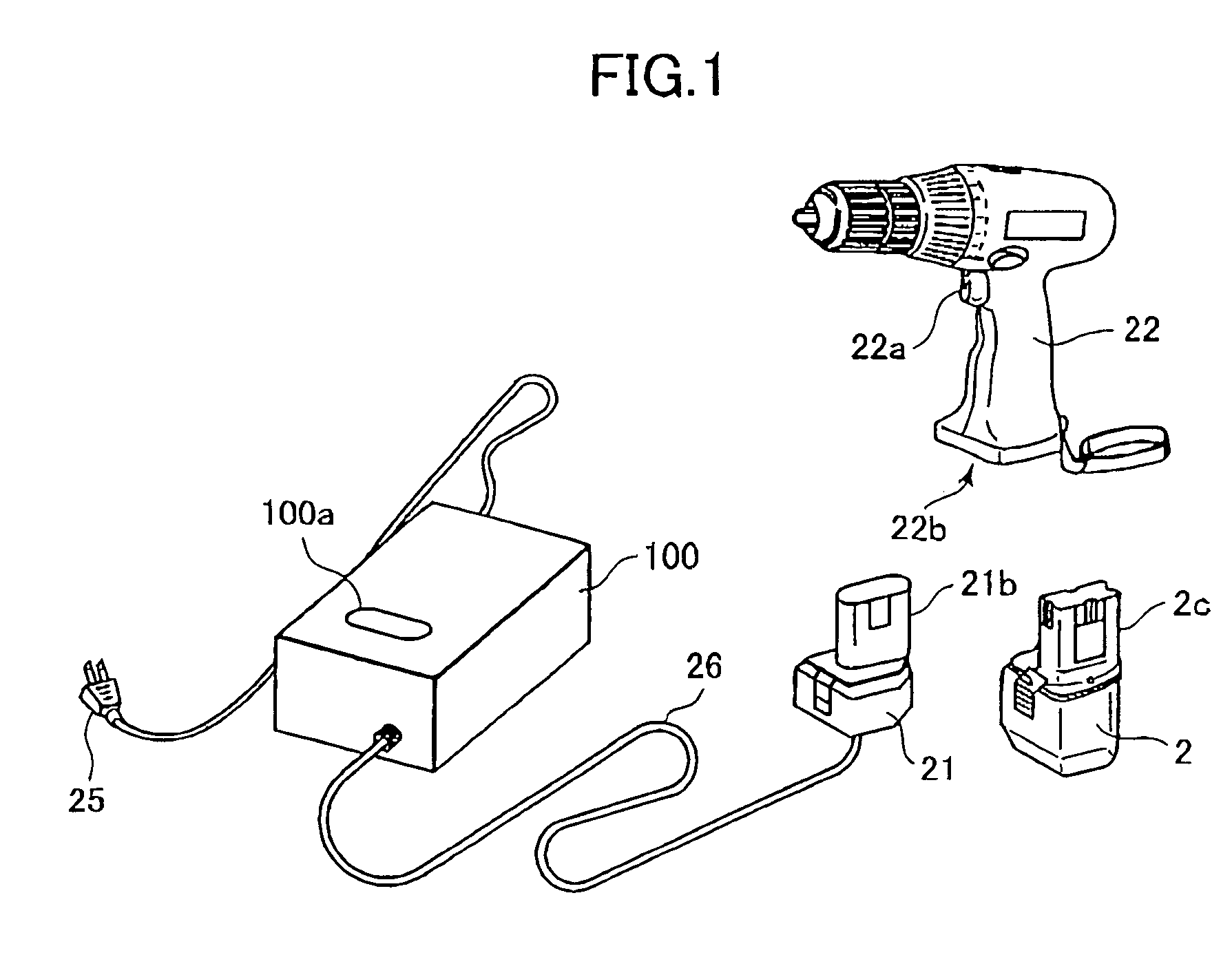
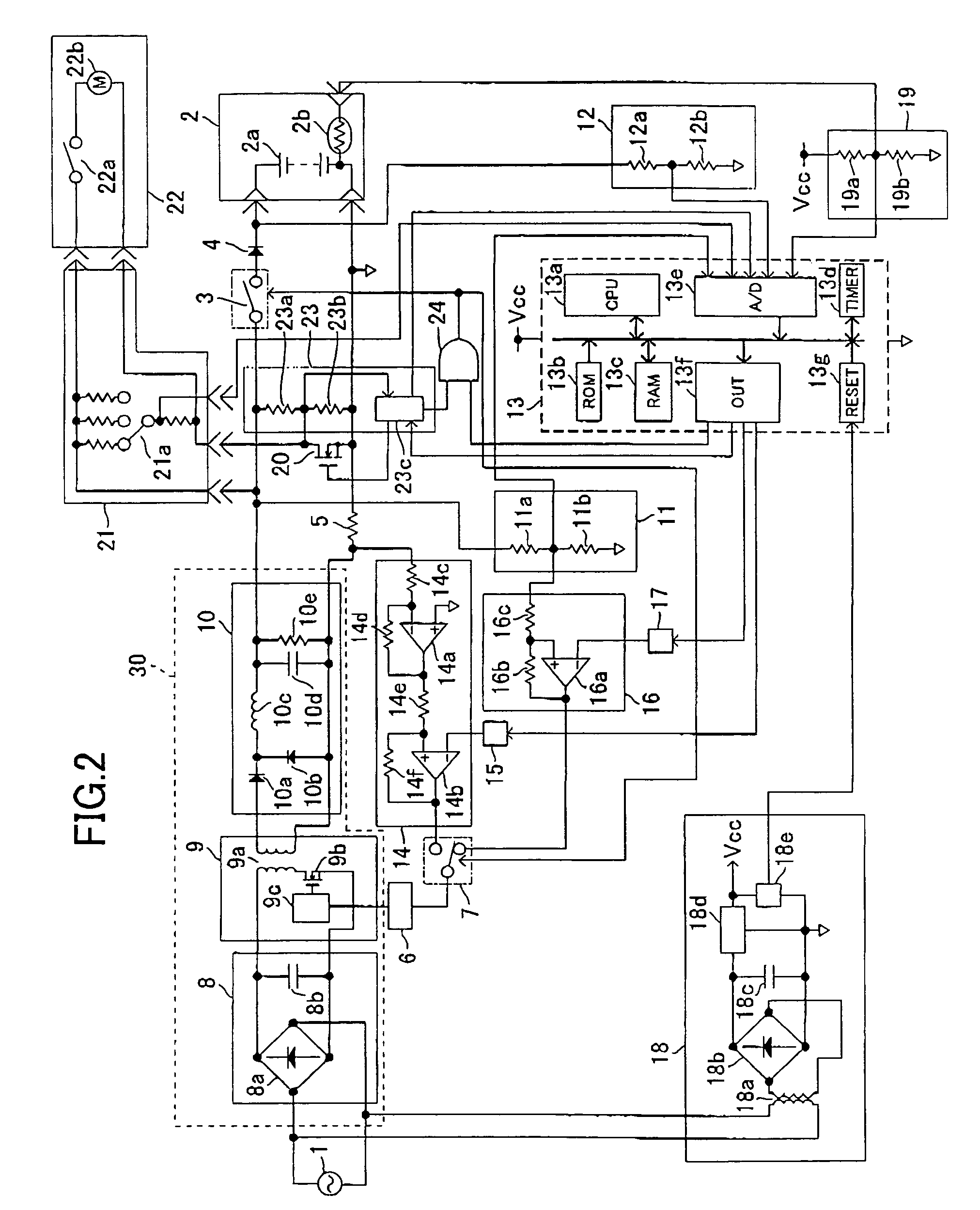
[0020]As shown in FIG. 1, a cordless power tool 22 is used with selective one of the DC power source unit and a battery pack 2. The cordless power tool 22 includes a power switch 22a. The battery pack 2 includes an insertion portion 2c that is detachably mountable into a handgrip recess 22b of the cordless power tool 22.

[0021]The DC power source unit includes a main unit 100, an AC cord 25, and an adapter 21. The AC cord 25 connects the main unit 100 to a commercial 100V alternating current (AC) power source. Also, an output cable 26 connects the main unit 100 to the adapter 21. The adapter 21 includes an adapter plug 21b which has the same shape as the insertion portion 2c of the battery pack 2. The adapter plug 21b is inserted into the handgrip recess 22b of the cordless power tool 22 in order to supply power to the power ...


PUM

PropertyMeasurementUnit
output voltageaaaaaaaaaa
poweraaaaaaaaaa
voltageaaaaaaaaaa

Abstract

A DC power source unit supplies a DC voltage to a power tool through an adapter when a power switch of the tool is turned ON and also charges a battery pack used as an alternative power source of the tool when the power tool is not operated. In order to prevent a rush current from flowing in a switch interposed between a switching power source circuit and the battery pack when charging the battery pack is commenced, the switch is rendered OFF when the output voltage from the switching power source is greater than the battery voltage. Charging the battery is started upon once lowering the output of the switching power source to a level lower than the battery voltage.

Description

BACKGROUND OF THE INVENTION[0001]1. Field of the Invention[0002]The present invention relates to a DC power source unit that can selectively charge a battery pack, which is used as a power source for a cordless power tool, and supply DC voltage to the cordless power tool through an adaptor shaped like the battery pack.[0003]2. Description of the Related Art[0004]Cordless power tools are convenient because they can be used anywhere without being restricted by the length of a power cable. However, whenever the battery runs low, the battery pack needs to be removed and charged or else replaced with another battery pack that has already been charged.[0005]A DC power source unit that converts alternating current to direct current can be used along with the battery pack. That is, the DC power source unit can be used when the cordless power tool is to be operated in a single place that has a source of alternating current, and the battery pack can be used when the cordless power tool is to ...

Claims


Application Information

Patent Timeline
Patent Type & Authority Patents(United States)
IPC IPC(8): H02M3/335H02J7/00H01F17/00H02J7/10
CPCH02J7/022H02J7/0031H02J7/02H02J2207/20H02J7/00304
Inventor TAKANO, NOBUHIROARADACHI, TAKAOHARADA, HIDEKAZUISHIMARU, KENROUTAKEDA, TAKESHI
Owner KOKI HLDG CO LTD
Why Eureka
Try Eureka