System and apparatus for power system utilizing wide temperature range heat sources

a technology of power system and heat source, which is applied in the direction of mechanical equipment, machines/engines, steam engine plants, etc., can solve the problems of low heat transfer coefficient of vapor to the intercooler tube, large and expensive high pressure heat exchanger, and negative impact on the economics of the entire system

Inactive Publication Date: 2007-04-03
KALINA POWER LTD
View PDF22 Cites 55 Cited by
  • Summary
  • Abstract
  • Description
  • Claims
  • Application Information

AI Technical Summary

Benefits of technology

[0010]The present invention also provides a bottoming cycle system including a heat recovery vapor generator subsystem (HRVG), a multi-stage energy conversion or turbine subsystem (T) and a condensation thermal compression subsystem (CTCSS). The turbine subsystem T includes a high pressure turbine or turbine stage (HPT) and a low pressure turbine or turbine stage (LPT). The HRVG includes five sections. The lower middle two sections comprise an intercooler. The CTCSS can be a simple condenser or a more complex condensation thermal compression subsystem designed to more efficiently condense a multi-component working fluid. The system is designed so that a spent stream exiting the HPT of the turbine subsystem T is through the intercooler to provide additional heat for vaporing the working fluid stream.

Problems solved by technology

Moreover, the intercooled stream in the prior art is in the form of a vapor, and therefore the heat transfer coefficient from the vapor to the intercooler tubes is low.
As a result, such an intercooler must be a very large and very expensive high pressure heat exchanger.
This in turn has a very negative impact on the economics of the entire system.

Method used


Image

  • System and apparatus for power system utilizing wide temperature range heat sources
  • System and apparatus for power system utilizing wide temperature range heat sources
  • System and apparatus for power system utilizing wide temperature range heat sources

Examples


Embodiment Construction

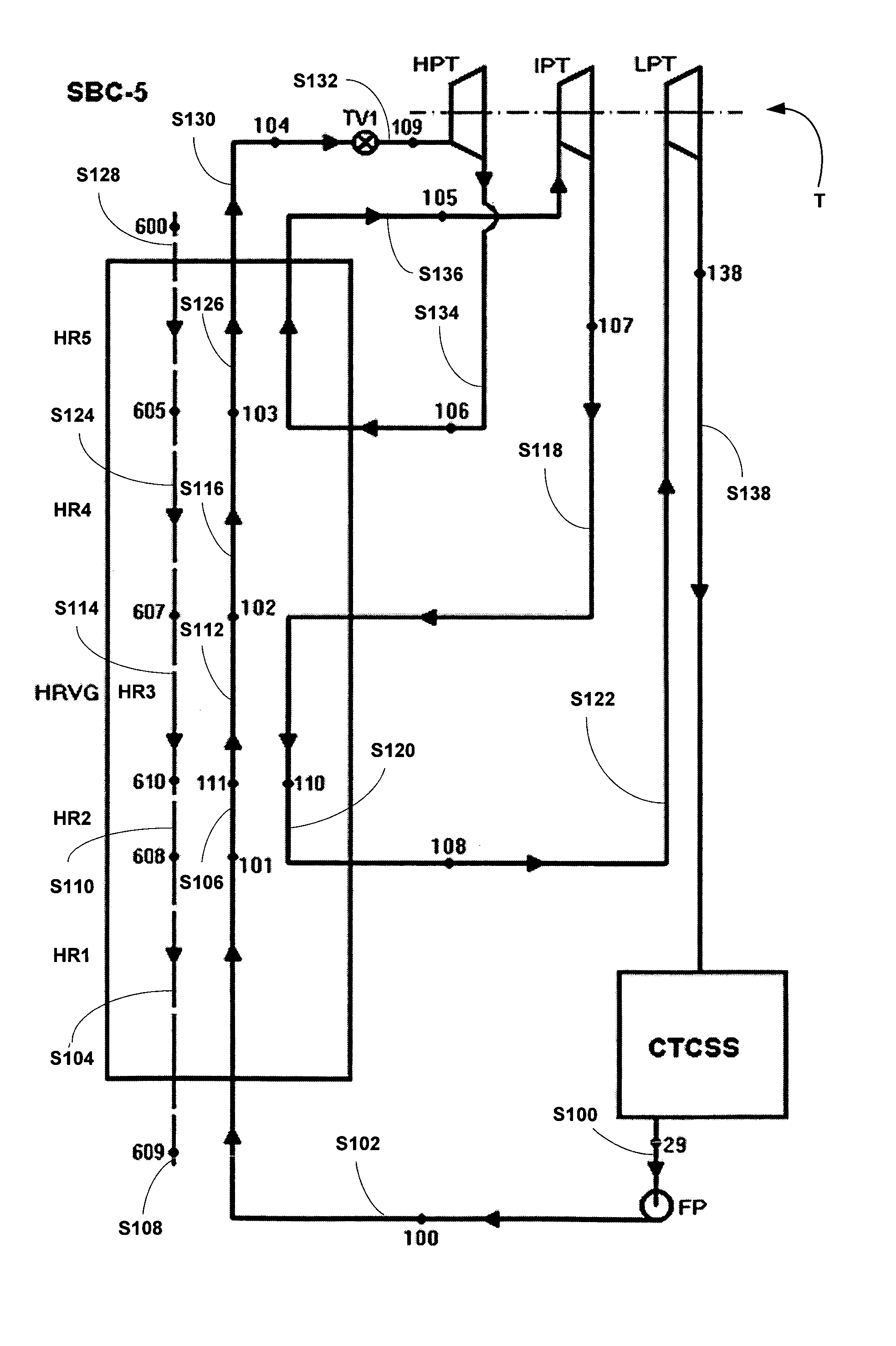
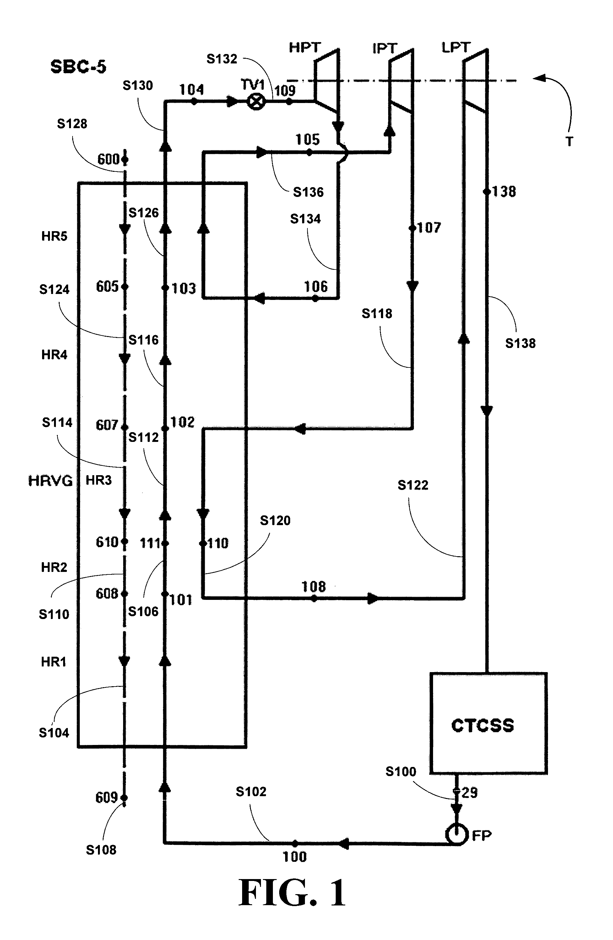
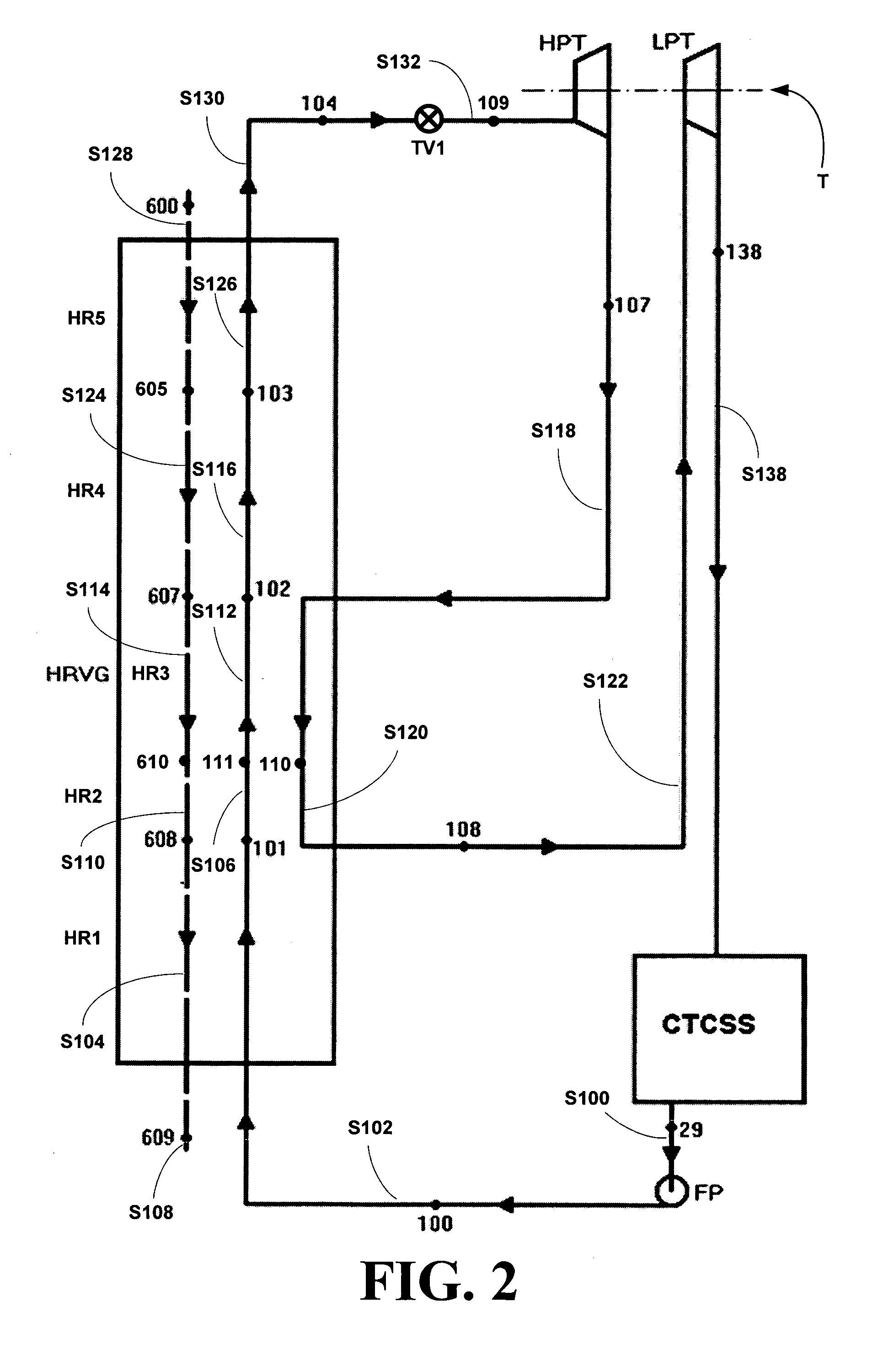
[0030]The inventors have found a new bottoming system can be constructed using a heat recovery vapor generator (HRVG) subsystem, a multi-stage energy conversion subsystem and a condensation thermal compression subsystem (CTCSS), where one or more of the streams exiting the stages are set back through different portions of the HRVG to be warmed before being forwarded to the next stage. The multi-stage energy conversion or turbine (T) subsystem includes at least a high pressure turbine and a low pressure turbine and preferably, an intermediate pressure turbine. Unlike the prior are systems, where the intercooler was a specialized separate piece of equipment with fairly high pressure drops, the intercooler of this system is built into the HRVG reducing pressure drops, while maintaining overall efficiency of 0.9982% of the prior art, yet increasing power output due to better utilization of the heat in the heat source, i.e., the heat source stream is cooled to a low temperature in the pr...


PUM


Abstract

A new method, system and apparatus for power system utilizing wide temperature range heat sources and a multi-component working fluid is disclosed including a heat recovery vapor generator (HRVG) subsystem, a multi-stage energy conversion or turbine (T) subsystem and a condensation thermal compression subsystem (CTCSS) and where one or more of the streams exiting the stages of the turbine subsystem T are sent back through different portions of the HRVG to be warmed and / or cooled before being forwarded to the next stage of the turbine subsystem T. The turbine subsystem T includes at least a high pressure turbine or turbine stage (HPT) and a low pressure turbine or turbine stage (LPT) and preferably, an intermediate pressure turbine or turbine stage (IPT).

Description

BACKGROUND OF THE INVENTION[0001]1. Field of the Invention[0002]The present invention relates to a bottoming cycle system for converting a portion of heat from a heat source stream, especially, an exhaust stream from an internal combustion engine, into usable mechanical and / or electrical power.[0003]More particularly, the present invention relates to a bottoming cycle system for converting a portion of heat from a heat source stream, especially, an exhaust stream from an internal combustion engine, into usable mechanical and / or electrical power, where the system includes a heat recovery vapor generator (HRVG) subsystem, a multi-stage energy conversion or turbine (T) subsystem and a condensation thermal compression subsystem (CTCSS) and where one or more of the streams exiting the stages of the turbine subsystem T are sent back through different portions of the HRVG to be warmed and / or cooled before being forwarded to the next stage of the turbine subsystem T. The turbine subsystem T...

Claims


Application Information

Patent Timeline
Patent Type & Authority Patents(United States)
IPC IPC(8): F01K25/06
CPCF01K25/065
Inventor KALINA, ALEXANDER I.
Owner KALINA POWER LTD
Why Eureka
Try Eureka