Vacuum cleaner

a vacuum cleaner and vacuum cleaner technology, applied in the direction of cleaning filter means, cable arrangements between relatively moving parts, separation processes, etc., can solve the problems of filter blockage, and easy drop in the function of air and dust separation, so as to improve the cleaning capability and reduce the windage

Inactive Publication Date: 2007-04-03
TOSHIBA TEC KK
View PDF33 Cites 81 Cited by
  • Summary
  • Abstract
  • Description
  • Claims
  • Application Information

AI Technical Summary

Benefits of technology

[0026]Swirl is inhibited from being caused in the separation. Additionally, since the flow of the dust-containing air does not invert or detour, windage is small. Therefore, since a capability of separation of the air and dust is inhibited from dropping, a cleaning capability can be improved.
[0033]The swirl is inhibited from being caused in the separation. Additionally, since the flow of the dust-containing air does not invert or detour, windage is small. Therefore, since the capability of the separation of the air and dust is inhibited from dropping, the cleaning capability can be improved.

Problems solved by technology

Therefore, the filter is clogged at an early stage, thus the function of separation of the air and dust easily drops.
Therefore, the filter is clogged at the early stage, and the function of the separation of the air and dust easily drops.
The dust that sticks to the surface of the exhaust filter while the motor blower is operating can therefore easily come off and falls.
This decreases the area of effective filter region, inevitably reducing the capability of the exhaust filter.
With the collision of the dust-containing air with the hose port opposed wall, turbulence is generated, and therefore windage is large.
Additionally, since the air current goes by the hose opposed wall, the windage is large.

Method used


Image

  • Vacuum cleaner
  • Vacuum cleaner
  • Vacuum cleaner

Examples


first embodiment

[0057]the present invention will be described hereinafter with reference to FIGS. 1 to 19.

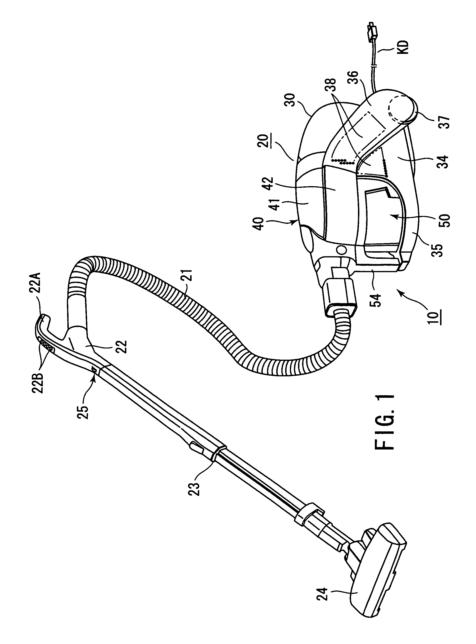
[0058]In FIG. 1, a vacuum cleaner shown by a reference numeral 10 includes a cleaner main body 20. This main body 20 is removably connected to one end of a flexible dust suction hose 21. The other end of the dust suction hose 21 includes a handling operation section 22. The handling operation section 22 includes a handle 22A. This handle 22A includes operation switches 22B for remote operation.

[0059]The handling operation section 22 is connected to an expandable / contractible extension pipe 23 so that the tube is attachable / detachable. A tip end of the extension pipe 23 is connected to an attachable / detachable draw-in port member 24. The dust suction hose 21, extension pipe 23, and draw-in port member 24 form an intake passage member 25.

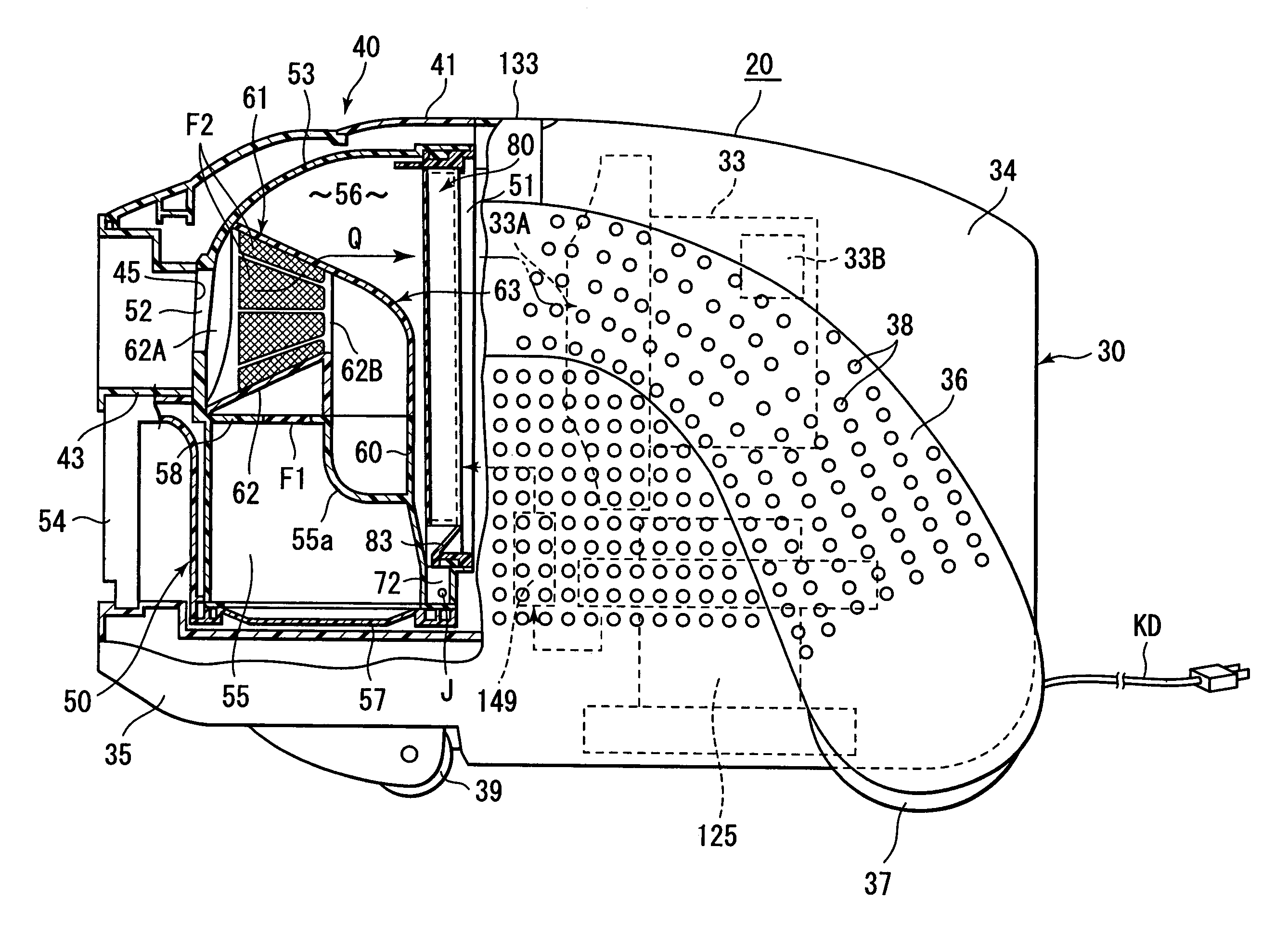
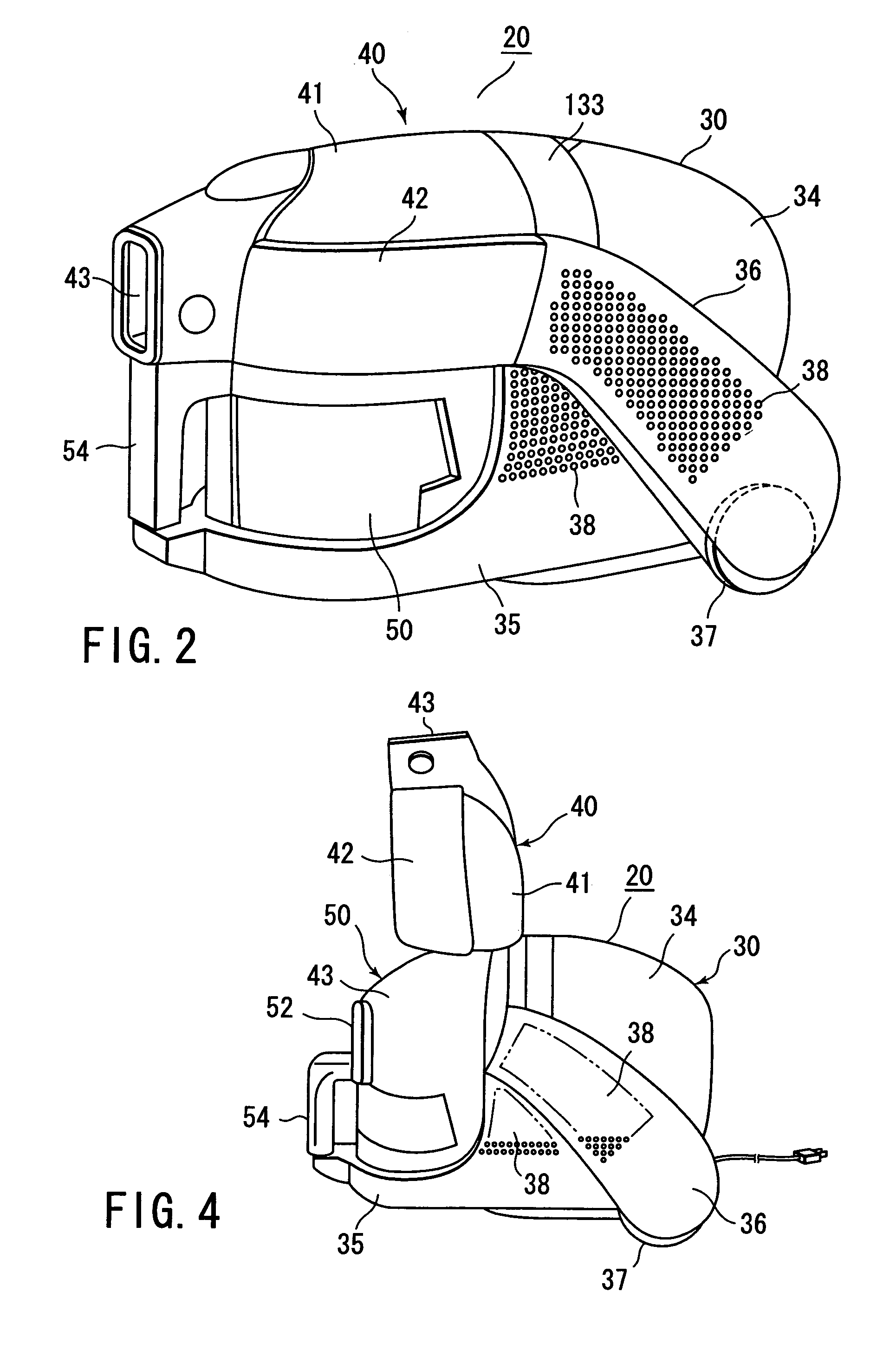
[0060]As shown in FIGS. 1 to 4, the cleaner main body 20 includes a main-body case 30, a dust cup 50, and a lid member 40. The dust cup 50 is disposed in the mai...

third embodiment

[0174]FIGS. 21 and 22 show the present invention. The third embodiment is basically the same as the first embodiment. Therefore, the same constitution as that of the first embodiment is denoted with the same reference numerals as those of the corresponding constitution, and the description is omitted. Since the third embodiment is different from the first embodiment in the lower frame section 81a and dust discharge means 83 of the filter 80, this respect will be described hereinafter.

[0175]As shown in FIG. 22, the closing portions 84a and cutout portions (dust through portions) 84b are alternately arranged in the lower frame section 81a. The lower frame section 81a does not include the oblique section employed in the first embodiment. Therefore, the lower frame section 81a is directly supported by the second dust accumulation section 72 as shown in FIG. 21 in a state in which the filter 80 is fitted into the opening 51. In this state, the closing portions 84a and cutout portions 84b...


PUM

PropertyMeasurementUnit
diameteraaaaaaaaaa
gas permeabilityaaaaaaaaaa
inertiaaaaaaaaaaa

Abstract

There is disclosed a vacuum cleaner including a dust separation section which separates air and dust flowing toward an intake port of a motor blower through a connection port of a cleaner main body. The dust separation section includes an air path forming member which performs a separation function. The forming member includes an introductory port, a derivative port, and an opening disposed between these. In the separation function, while dust-containing air flows toward the derivative port from the introductory port, a part of the air is sucked by the motor blower through the opening. Accordingly, the air is separated from the dust which goes straight in the air path forming member with inertia.

Description

CROSS REFERENCE TO RELATED APPLICATIONS[0001]This is a Continuation Application of PCT Application No. PCT / JP03 / 03365, filed Mar. 19, 2003, which was published under PCT Article 21(2) in Japanese.[0002]This application is based upon and claims the benefit of priority from prior Japanese Patent Applications No. 2002-317919, filed Oct. 31, 2002; No. 2002-348564, filed Nov. 29, 2002; and No. 2003-009103, filed Jan. 17, 2003, the entire contents of all of which are incorporated herein by reference.BACKGROUND OF THE INVENTION[0003]1. Field of the Invention[0004]The present invention relates to a vacuum cleaner including a first dust separation section for separating dust in sucked dust-containing air, and a second dust separation section disposed on a downstream side of the first dust separation section, particularly to a vacuum cleaner in which the first dust separation section uses inertia of the dust to separate the dust.[0005]2. Description of the Related Art[0006]A cyclone vacuum cl...

Claims


Application Information

Patent Timeline
Patent Type & Authority Patents(United States)
IPC IPC(8): B01D45/12A47L9/00A47L9/10A47L9/12A47L9/16A47L9/20A47L9/26B01D50/00
CPCA47L9/102A47L9/122A47L9/165A47L9/1666A47L9/1683A47L9/20A47L9/26B01D46/10B01D46/521B01D50/002Y10S55/03B01D50/20A47L9/10A47L9/16
Inventor TAKEMOTO, RITSUOTANAKA, MASATOSHIYOKOYAMA, HIROSHISUZUKI, HITOSHIEBE, KIYOSHITSUCHIYA, YOSHIHIROTANAKA, AINAKATOGAWA, YASUSHIOSHIMA, IKUOKINOSHITA, YUSUKEMAEDA, YUTAKA
Owner TOSHIBA TEC KK
Why Eureka
Try Eureka