
Portable terminal

a terminal and portability technology, applied in the direction of hinges, wing accessories, machine supports, etc., can solve the problems of large size, long life, and large size of portable wireless telephone sets "a"

Inactive Publication Date: 2007-04-03
SONY ERICSSON MOBILE COMM JAPAN INC
View PDF14 Cites 11 Cited by
  • Summary
  • Abstract
  • Description
  • Claims
  • Application Information

AI Technical Summary

Benefits of technology

[0012]A portable terminal device according to the present invention aims to maintain the miniaturization of the said portable terminal device, and to prevent breakage by a load.
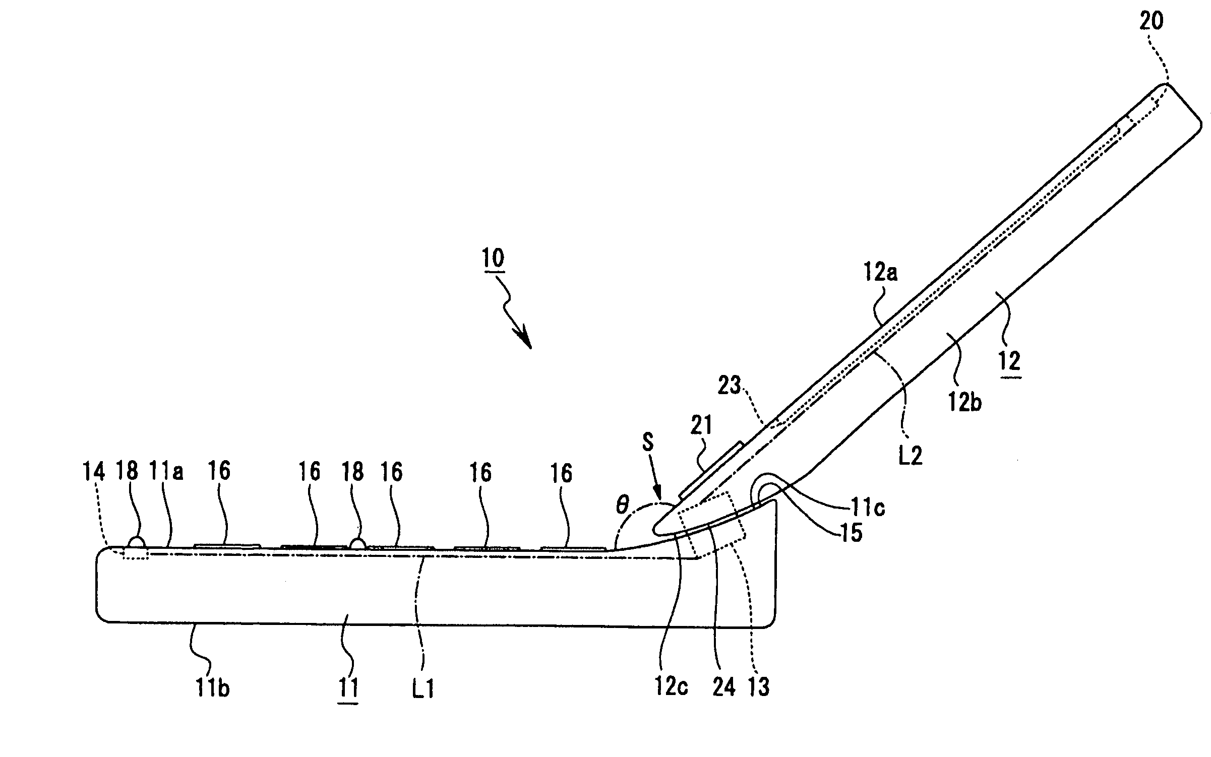
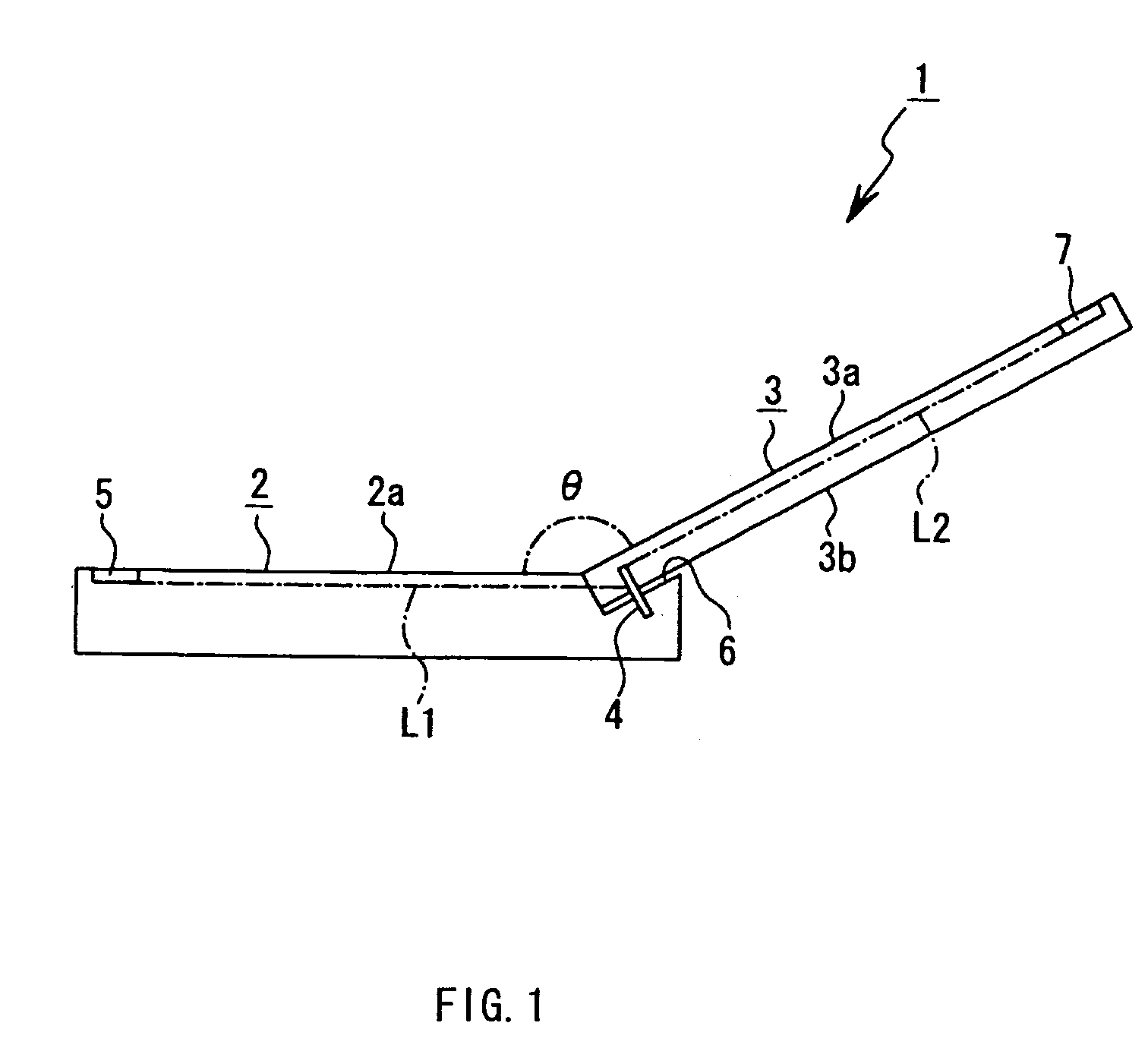
[0014]Accordingly, in the portable terminal device according to the present invention, even if load is charged on the first housing and the second housing when the open state where the first housing and the second housing are mutually tilted via the hinge part is formed, the angle formed by the first housing and the second housing in the said open state can be changed by the tilt angle changing means, thereby, the breakage of the first housing and the second housing by the said load can be prevented, and a separation between the first housing and the second housing can be prevented.

Problems solved by technology

Then, to improve the usability, it can be considered that as a portable wireless telephone set a′ shown in FIGS. 42 and 43, a projecting part “j” is provided by making the part having the microphone part “b” in the first housing “c” project, however, since the projecting-part “j” is provided, the length of the first housing “c” becomes longer: it causes a problem that the portable wireless telephone set “a” becomes a large size.
Note that, this large size problem similarly arises also in the case where the part having the speaker part “d” in the second housing “e” is projected, without projecting the part having the microphone part “b” in the first housing “c”.
However, although the open / close type portable information terminal is designed so that, in the state where the display part housing and the operating part housing are opened, they form a predetermined angle θ (180° or less), also there is a problem that if force is applied to the display part housing, the connecting member receives excessive load and is apt to be broken.

Method used


Image

  • Portable terminal
  • Portable terminal
  • Portable terminal

Examples


first embodiment

[0017]FIG. 3 is a diagram to show a portable terminal device according to the present invention with FIGS. 4 to 24, and is a perspective view of a portable wireless telephone set in an open state.

[0018]FIG. 4 is a perspective view of the portable wireless telephone set in the state where a second housing is being turned.

[0019]FIG. 5 is a perspective view of the portable wireless telephone set in a close state.

[0020]FIG. 6 is an enlarged side view of the portable wireless telephone set in the open state.

[0021]FIG. 7 is an enlarged side view of the portable wireless telephone set in the close state.

[0022]FIG. 8 is an enlarged plane view of the first housing.

[0023]FIG. 9 is an enlarged side view of the first housing, of which a part is shown in section.

[0024]FIG. 10 is an enlarged bottom view of the second housing.

[0025]FIG. 11 is an enlarged side view of the second housing, of which a part is shown in section.

[0026]FIG. 12 is an illustration showing the state where the portable wirele...

second embodiment

[0039]FIG. 25 is a diagram showing a portable terminal device according to the present invention with FIGS. 26 and 27, and is a perspective view of a portable wireless telephone set in an open state.

[0040]FIG. 26 is an enlarged perspective view illustrating a part of the portable wireless telephone set in the open state from a different angle from FIG. 25.

[0041]FIG. 27 is a front view of the portable wireless telephone set in a close state.

third embodiment

[0042]FIG. 28 is a diagram showing a portable terminal device according to the present invention with FIGS. 29 to 33, and is a perspective view of a portable wireless telephone set in an open state.

[0043]FIG. 29 is an enlarged side view of the portable wireless telephone set in the open state.

[0044]FIG. 30 is an enlarged side view of the portable wireless telephone set in a close state.

[0045]FIG. 31 is an enlarged front view of the portable wireless telephone set in the close state.

[0046]FIG. 32 is a diagram showing the modified example of the third embodiment of the portable terminal device according to the present invention with FIG. 33, and is a perspective view of a portable wireless telephone set in an open state.

[0047]FIG. 33 is an enlarged side view of the portable wireless telephone set in a close state.


PUM


Abstract

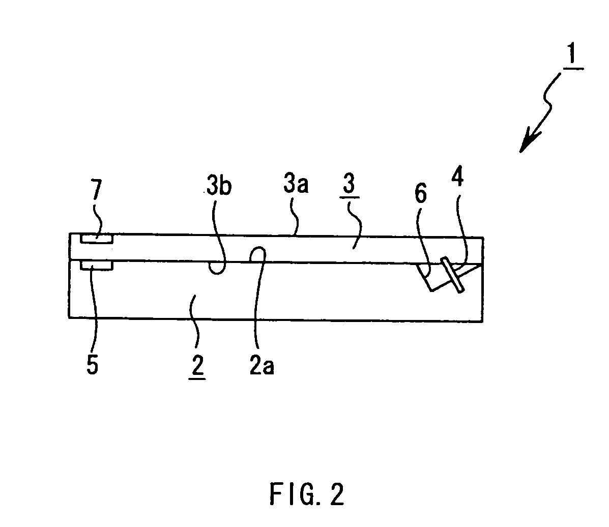
To improve usability while maintaining miniaturization, in a portable terminal device in which one end part of a first housing having an operating part and one end part of a second housing having a display part are turnably connected by a hinge part, an open state where the surface of the display part and the surface of the operating part are opened at a predetermined angle is formed by turning the first housing or the second housing by the hinge part from a close state where the first housing and the second housing are overlapped with each other and the operating part surface and the display part surface are facing to the same direction, and the hinge part has tilt angle changing means that is tiltably supported to the first housing or the second housing and can change the angle in the open state.

Description

TECHNICAL FIELD[0001]The present invention relates to a portable terminal device, and more particularly, relates to the technical field of a portable terminal device in which a first housing having a microphone part and a second housing having a speaker part are connected via a hinge shaft in freely turnable to the shaftwise direction of said hinge shaft.BACKGROUND ART[0002]Portable terminal devices, for example, portable wireless telephone sets have been popularized by the development of mobile telephone systems in recent years. In portable wireless telephones sets, there is a type in which a first housing having a microphone part and a second housing having a speaker part are turnably connected via a hinge shaft, however, as such type of portable wireless telephone sets, some are designed so that the first housing and the second housing are turnably connected to the shaftwise direction of the hinge shaft, and the microphone part and the speaker part face to the same direction in a...

Claims


Application Information

Patent Timeline
Patent Type & Authority Patents(United States)
IPC IPC(8): H04M1/00H04B1/38E05D3/02F16C11/04F16M11/10H04M1/02H04W88/02
CPCF16M11/10H04M1/0233H04M1/0227F16M13/005E05D3/022E05Y2900/606F16M2200/041E05Y2999/00H04B1/38
Inventor TANINAI, MINORU
Owner SONY ERICSSON MOBILE COMM JAPAN INC
Learn More