Eureka AIR delivers breakthrough ideas for toughest innovation challenges, trusted by R&D personnel around the world.

Hair holding cap for a hair braider

a hair braider and holding cap technology, applied in the field of hair braiding cap, can solve the problems of affecting the uniformity of braiding work, so as to achieve uniformity and tidiness of braiding hair

Inactive Publication Date: 2007-04-10
LEE MYUN WOO
View PDF15 Cites 1 Cited by
  • Summary
  • Abstract
  • Description
  • Claims
  • Application Information

AI Technical Summary

Benefits of technology

[0010]It is an object of the present invention is to provide a hair gripping cap whose structure gives a constant and proper tension to hair strands braided mechanically until the hair strands are completely released therefrom.
[0012]The hair gripping cap in accordance with the present invention applies a constant and proper tension on hair being mechanically braided until the hair is completely braided and released from a hair braiding machine, thereby ensuring a uniformity and tidiness of braided hair.

Problems solved by technology

This braiding work requires considerable time and cost.
Also, as the quality of such a manually braided hair style totally depends on the worker's skill, it may not be uniform.
However, if the friction between the nozzle 106a and the hair strands is excessive because of a smaller inner diameter of the nozzle 106a, it hinders the hair strands from being drawn out of the nozzle 106a smoothly, thereby tensioning the hair strands more excessively.
This excessive tension on the hair strands gives pains to the person and might stop a motor of the driving unit 200 as well.
These loosened hair strings give untidiness to the finished hair style.
Conversely, if the friction force is not sufficient, the hair strands cannot be held in a constant tension so that some hair strings are drawn out, through the nozzle 106a, more than the shortened length by braiding, which leads to bumpy braided hair.
This also looks untidy.

Method used


Image

  • Hair holding cap for a hair braider
  • Hair holding cap for a hair braider
  • Hair holding cap for a hair braider

Examples


Embodiment Construction

[0028]Referring now to the drawings, a preferred embodiment of the present invention will be described.

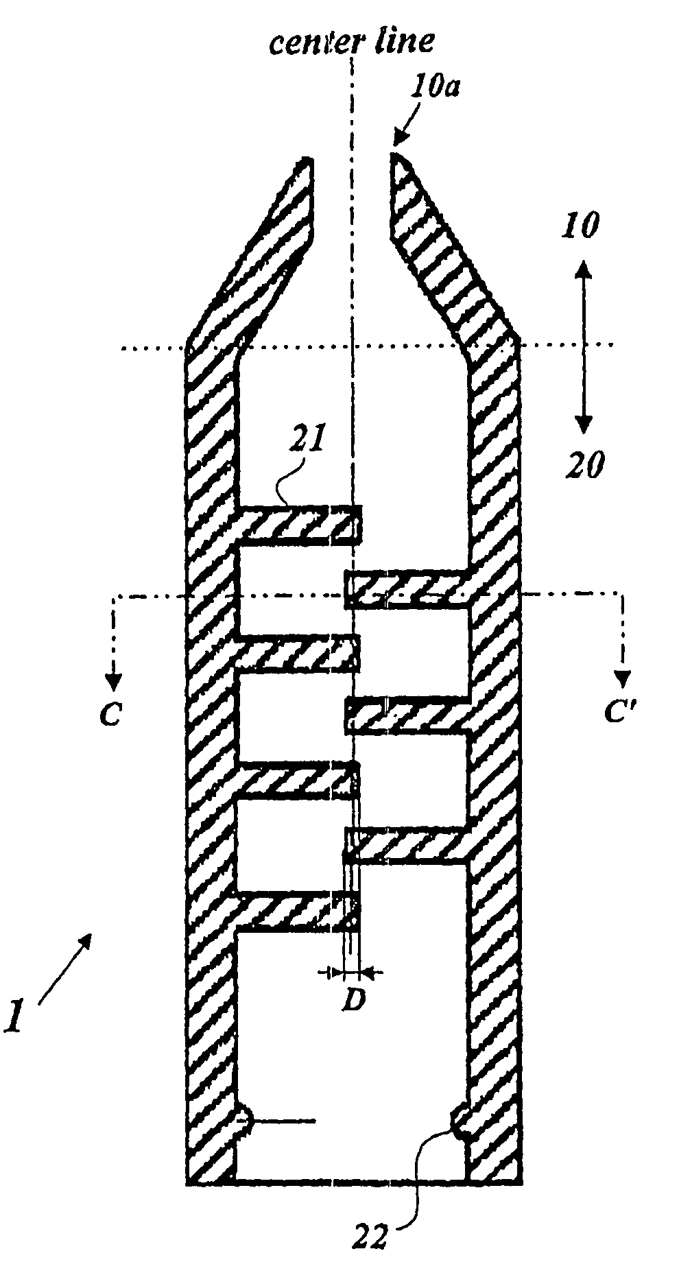
[0029]As shown in FIGS. 3A and 3B, a cap according to the present invention comprises a tapered head portion 10 having a nozzle 10a to pass strands of hair therethrough; and a cylindrical body portion 20, coaxially extended from the head portion 10 in one piece, having a plurality of inner partition walls 21 applying a constant and proper friction to hair strands passing thereby zigzag. An annular rib 22 is radially extended from the inner side wall of the body portion 20 to have the cap 1 fitted on a hair accommodating member 100 of FIG. 1B to a predetermined depth. The head portion 10 and the body portion 20 are made of elastic rubber materials.

[0030]Each partition wall 21 is horizontally extended from the inner side wall of the body portion 20 to define an opening for hair to pass through and has an configuration of almost semi-circular plate slightly larger than a half of the f...


PUM

PropertyMeasurementUnit
thicknessaaaaaaaaaa
thicknessaaaaaaaaaa
deflection angleaaaaaaaaaa

Abstract

The present invention relates to a hair gripping device to be mounted on a hair accommodating tube to grip a bundle of hair in a proper friction force during hair braiding by a hair braiding machine. The present hair gripping device comprises a tapered head portion having a nozzle for the bundle of hair to pass through; and a body portion, extended from the head portion in one piece, having a plurality of inner partition walls to give the bundle of hair a zigzag, spiral, or helical bends, thereby tensioning the bundle of hair properly during a braiding and / or releasing it smoothly at the end of braiding. Accordingly, a uniform and tidy, style of braided hair is obtained.

Description

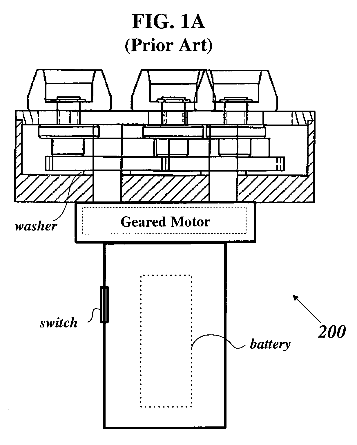
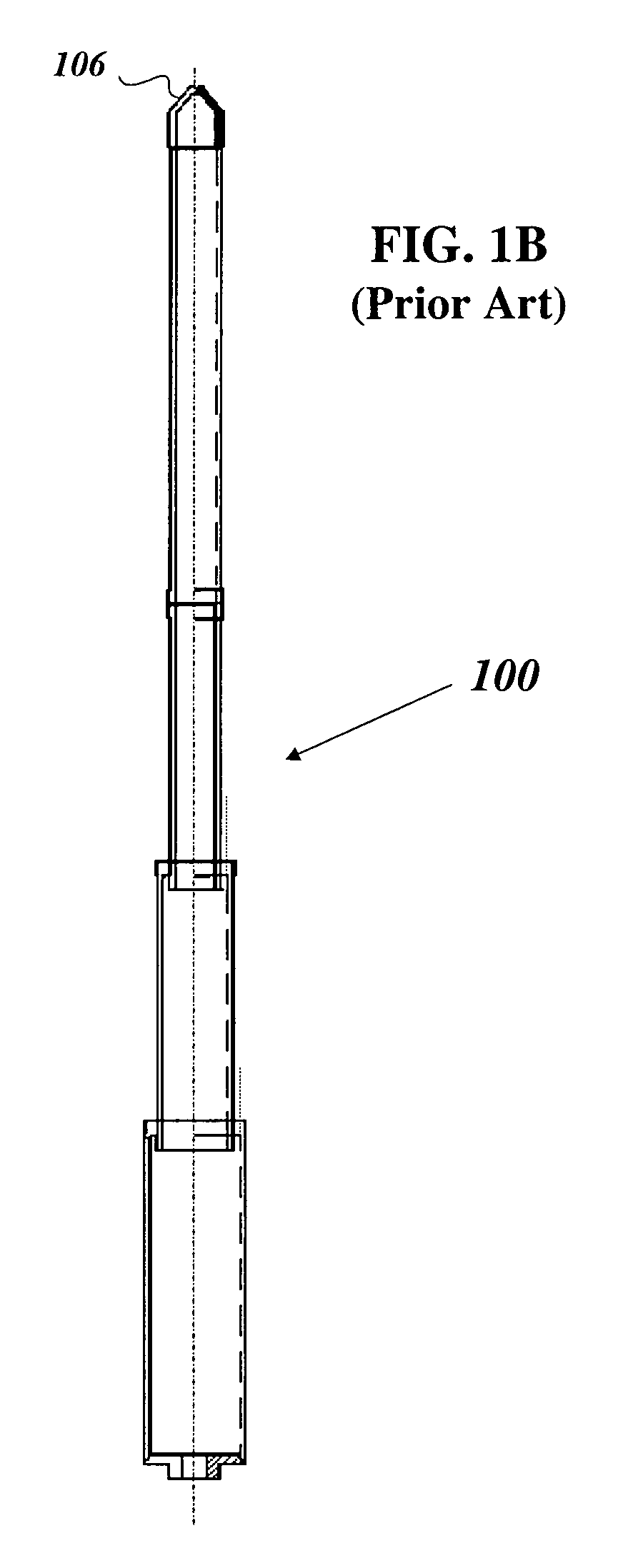
1. TECHNICAL FIELD[0001]The present invention relates to a hair gripping device, mounted on a hair accommodating tube detachably combined with a hair braiding machine, to grip strands of hair in a proper friction force during hair braiding with a hair braiding machine.2. BACKGROUND ART[0002]Usually, hair is manually braided by a person other than the one who is obtaining a desired hair style. This braiding work requires considerable time and cost. Also, as the quality of such a manually braided hair style totally depends on the worker's skill, it may not be uniform.[0003]Therefore, a hair braiding machine braiding a plurality of strands of hair into one braid mechanically was developed and filed in KIPO (Korea Industrial Property Office) on the Jan. 18, 2000 with Application No. 2000-4184.[0004]As shown in FIGS. 1A and 1B, the hair braider generally; comprises a driving unit 200 and three hair accommodating members 100 mounted on the driving unit 200 and driven in a figure eight ‘8’...

Claims


Application Information

Patent Timeline
Patent Type & Authority Patents(United States)
IPC IPC(8): D04C7/00A45D7/00A45D2/00A45D24/34
CPCA45D2/00A45D2002/005D04B7/00
Inventor LEE, MYUN WOO
Owner LEE MYUN WOO
Why Eureka
Eureka Blog
Learn More