
Device for measuring volume change of at least one textile fiber band

A technology of textile fiber and volume change, which is applied in the field of equipment devices, and can solve the problems of not considering the geographical area and the reduction of precision

Active Publication Date: 2009-10-28
托姆希克有限公司
View PDF0 Cites 6 Cited by
  • Summary
  • Abstract
  • Description
  • Claims
  • Application Information

AI Technical Summary

Problems solved by technology

[0015] This conversion inevitably results in a slight loss of precision
[0016] However, since analog sensors show different readings depending on the air conditioning in the building, even regardless of the geographic area of ​​the building in which the device is placed, this reduction in accuracy must be compared to the fact that analog sensors are often subjected to environmental conditions such as temperature and humidity. Considering the factors affecting the situation together

Method used


Image

  • Device for measuring volume change of at least one textile fiber band
  • Device for measuring volume change of at least one textile fiber band
  • Device for measuring volume change of at least one textile fiber band

Examples


Embodiment Construction

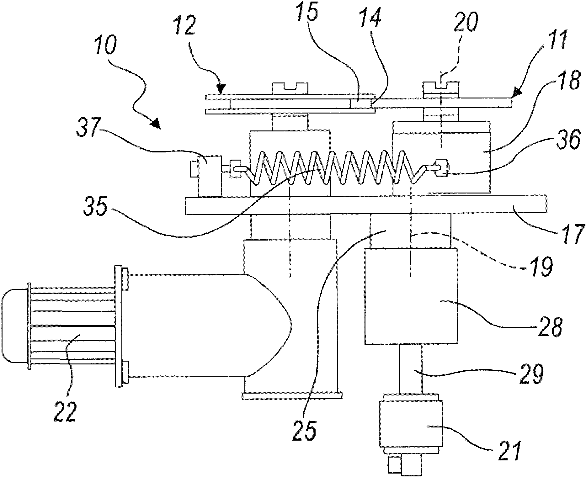
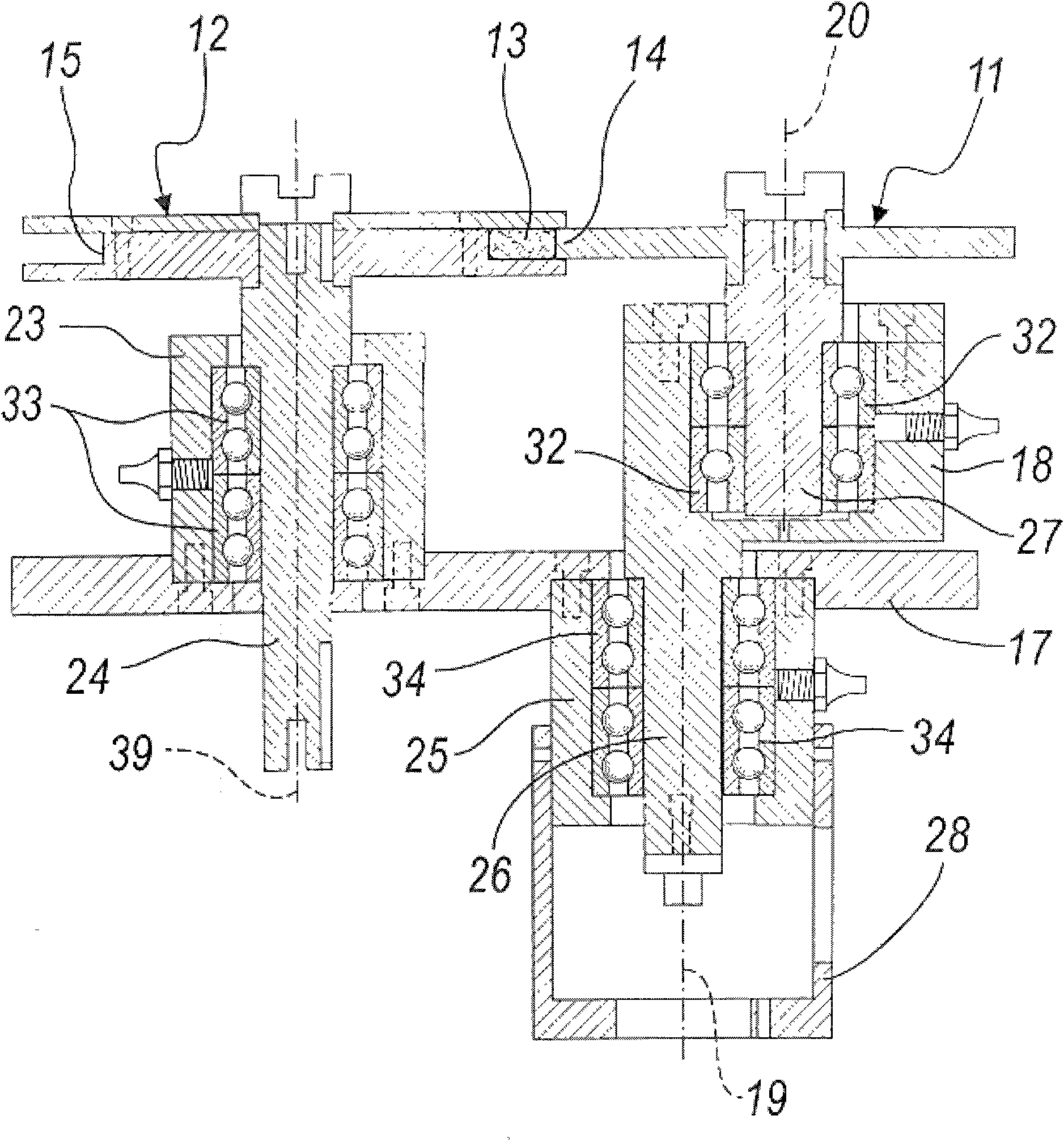
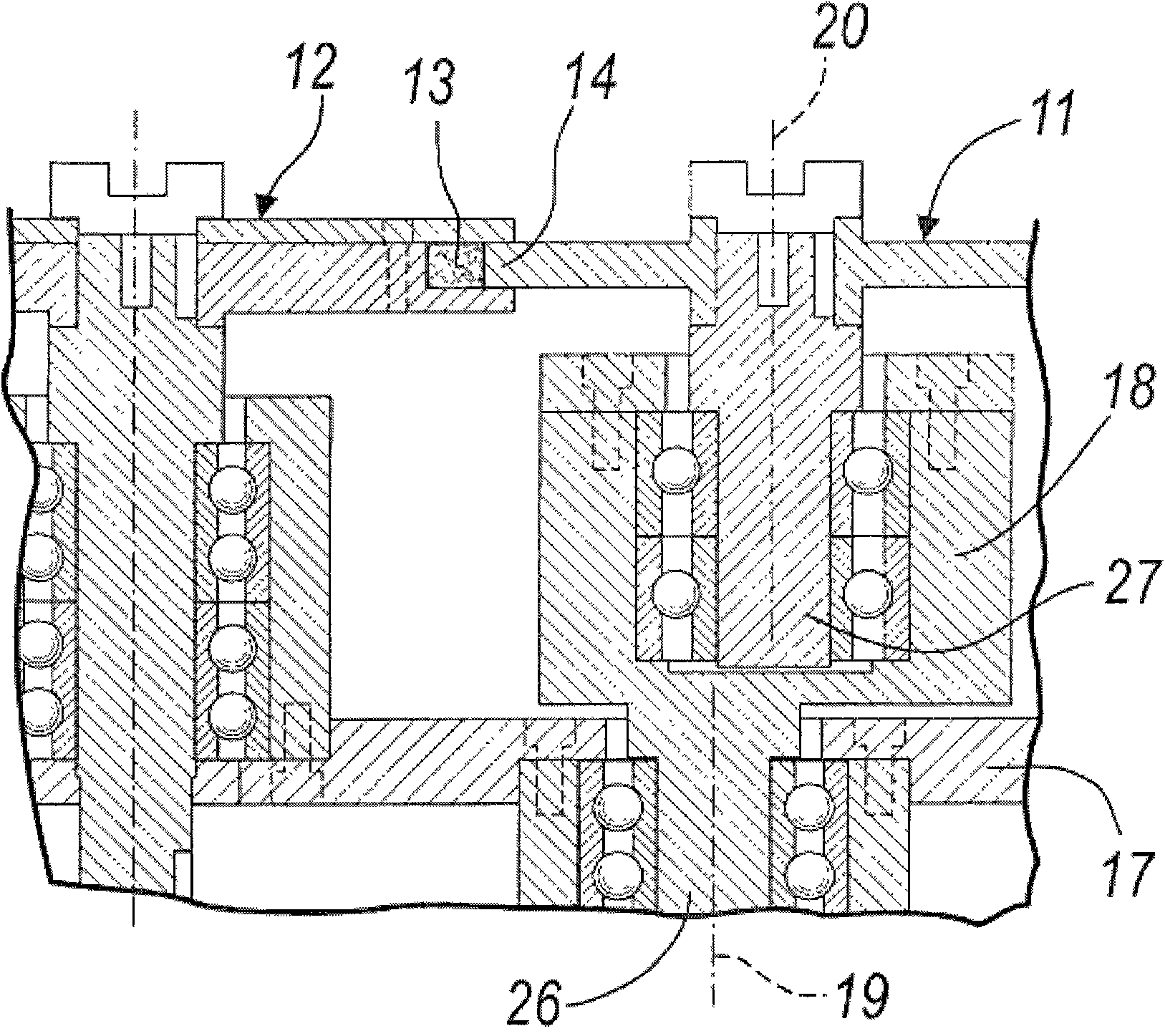
[0030] With reference to the above-mentioned figures, the device for measuring the volume change of at least one textile fiber strip according to the invention is indicated generally by the reference numeral 10 .

[0031] The device 10 includes a first movable wheel 11 and a second fixed wheel 12 with parallel wheel axles and variable wheel pitch, and between the first movable wheel 11 and the second fixed wheel 12 is slidably pulled at least one textile fiber belt 13 .

[0032] The first wheel 11 of these wheels is adapted to fit in the annular groove 15 of the second wheel 12 with its circumferential ring 14 , which is opened at the outer rim of the second wheel 12 and has a shape corresponding to the circumferential ring 14 .

[0033] The wheels 11 , 12 are pressed against each other by elastic means (described in detail below) to allow the first movable wheel 11 to move away / toward the second wheel 12 depending on the instantaneous cross-section of the at least one belt 13...


PUM


Abstract

The invention relates to a device for measuring volume change of one or a plurality of textile fiber bands, which comprises a first movable wheel and a second fixed wheel, wherein the wheel shafts of the first movable wheel and the second fixed wheel are parallel, and the wheel center distance between the first movable wheel and the second fixed wheel can be changed. At least one textile fiber band is pulled between the first movable wheel and the second fixed wheel in a sliding mode. A circumferential ring of the first movable wheel is matched in an annular groove, wherein the annular groove is arranged at the outer rim of the second fixed wheel, and the shape of the annular groove corresponds to that of the circumferential ring. The first movable wheel and the second fixed wheel are pressed together by an elastic device to enable the first movable wheel to move away from or move to the second fixed wheel according to the instant section of at least one band. The band is pressed in the groove of the second fixed wheel by the circumferential ring of the first movable wheel, and the first movable wheel is connected to a measuring device, wherein the second fixed wheel is pivoted on a supporting member which is integrated with an equipment stand of an installation device; the first movable wheel is supported by an eccentric element and is pivoted to the eccentric element; the eccentric element is pivoted on the supporting member; and a rotating shaft line of the eccentric element is parallel but not coincident with a shaft line of the first movable wheel.

Description

technical field [0001] The present invention relates to a device for measuring the volume change of at least one textile fiber ribbon, in particular a device for drawing frames, cards, combers and the like. Background technique [0002] Textile fibers can be natural like cotton and other natural fibers, or synthetic. [0003] Currently so-called "tongue and groove" devices are used for quality monitoring and automatic adjustment of textile industry equipment such as draw frames, cards, combers, etc. [0004] Such devices generally comprise two wheels with parallel axles of variable track distance between which at least one textile fibre band is slidably drawn. [0005] The first wheel of the two wheels is fitted in the annular groove of the second wheel with its circumferential ring. The annular groove is opened at the outer rim of the second wheel and has a shape corresponding to the circumferential ring. [0006] The two wheels are pressed against each other by elastic m...

Claims


Application Information

Patent Timeline
IPC IPC(8): G01B21/00D01G15/12D01G19/06
Inventor 托姆希克·西尔万
Owner 托姆希克有限公司
Learn More